
Vector Robotics Retreat 2026
A weekend of frankly unbelievable progress

Intro
We're hot off the back of the 2026 retreat (or at least the first one) and the vibes are great. Strap in, this is probably going to be a lengthy post, and even still there's a lot of detail that I'll cover in a couple of future posts since I can't do their complexity justice here.
In stark contrast to the 2025 retreat, this time was a blitz of major milestone achievement. The last one, while it was great fun and made some good progress, was plagued with what felt like constant issues that took many hours or days in some cases to fix - it shortcut what would have likely been weeks or months of time otherwise but in terms of what we had to show for it, there just wasn't anything like we had been hoping for. Sure there were still plenty of issues we ran into this time, but I can't think of any that took more than around an hour to solve, so this time around felt a lot more like a series of satisfying challenges to complete rather a relentless grind against problems that wouldn't yield.
One thing to note here is that I'm only going to cover the embedded software progress (with some hints of electronics & mechanical hardware) - loosely aligned with my focus on the retreat. In between brief stints of supporting/pestering me, Henry was largely working on the high-level software (which also made big leaps and bounds), but nothing there has been covered on the blog yet, so mentioning the progress now would be big spoilers for the posts that he isn't going to write 😜
So with that primer done, lets get into the details of what we got up to.
Day 1
This time we left after work on the Friday, so most of the day was already gone.
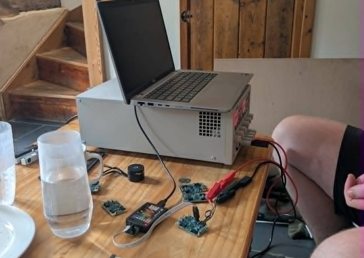
The only thing to mention before we get into day 1 proper, is that in the space between my last post about the prep and now is that I'd finished up assembly of the 5 RevC motor control boards I'd ordered. After rotating the diodes, that had been assembled the wrong way round, they powered on nicely on the first go! I was then briefly bamboozled why the software wasn't running after programming, before remembering that I need to set the option bytes to tell it to ignore the BOOT0 pin that has an I2C bus pull-up resistor - gets me every time (although at least I only had to think for about 5-10 minutes this time). After that everything seemed to run fine on the first board, with a couple of promising flashing LEDs, except I couldn't confirm this as I'd removed the UART connector on this revision anticipating that CAN messaging would be working by this point (and then forgot about that fact).
On the non-technical front we:
- Did a big Tesco run, with an absolutely hilarious self-service conveyor belt style checkout station that I've never seen anywhere before, and caved to too many impulse buys
- Went down a super bumpy gravel track past/through a Christmas tree farm (and some massive piles of poo) that we later learned was not the only way of getting to the airbnb
- Made some cracking quesadillas which involved multiple Guinness deglazings of the
nonstick pan - Made acquaintance with the local fly population which was foreshadowed by the 2x UV fly traps present in the living room
So no real technical progress on day 1, but we were nicely prepped for a good day of progress on the Saturday.
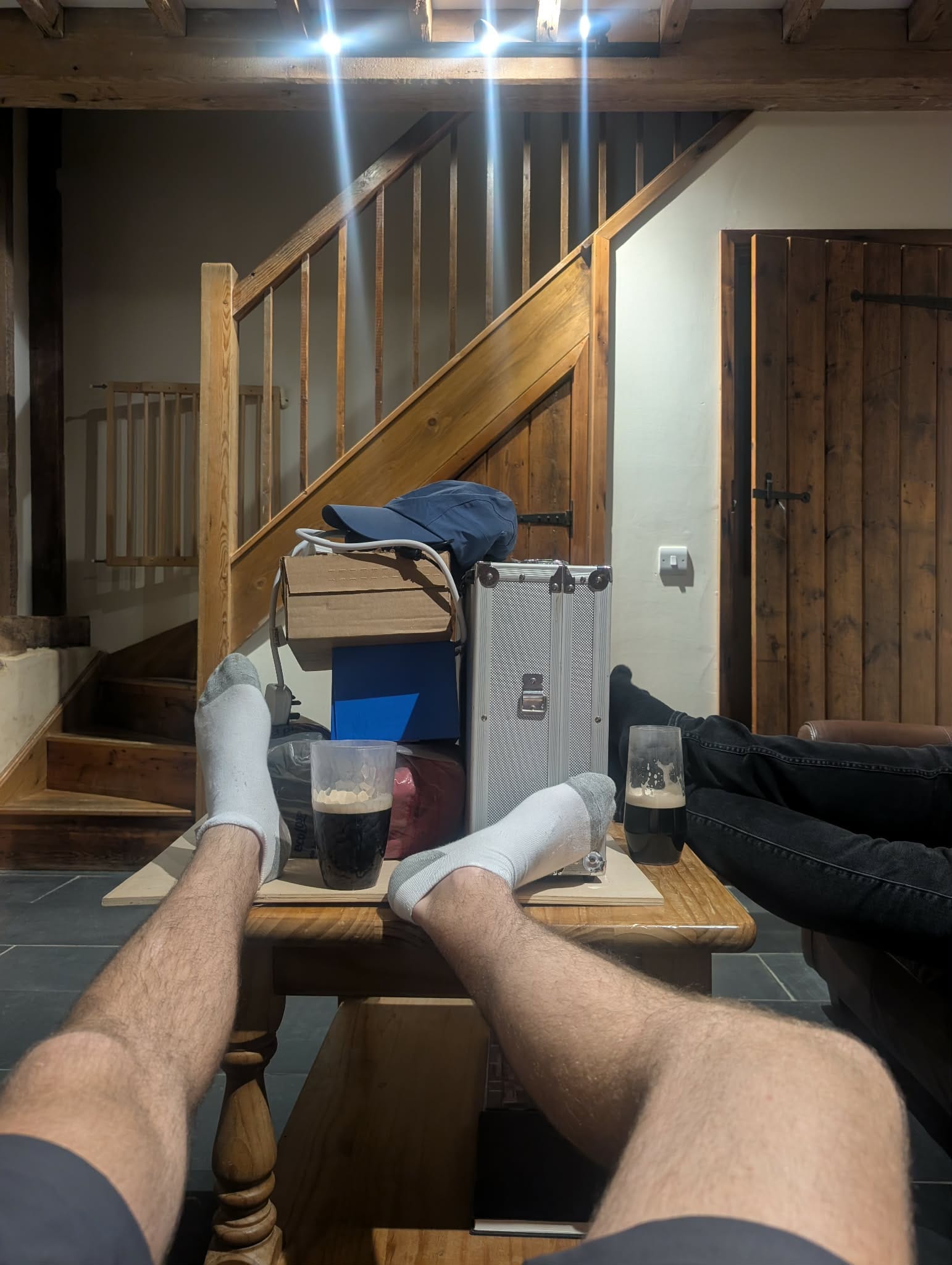
Feet up with a pile of robot parts and a couple pints of Guiness, and a well stocked fridge door of snacks
Day 2
And what a day of progress it was.
Multiple times I struggled to reconcile that it was still Saturday, and how different the levels of progress between morning and afternoon/evening. Brace yourself, there's a lot.
CMSIS v2 RTOS
So there's a lot I could talk about here, but I'll try to just scrape the surface and do a follow up post or something else later.
What is an RTOS?
An RTOS (Real Time Operating System) is basically a bit of software that you include which runs a scheduler that then facilitates running multiple tasks/thread/processes (probably some pedantic differences between these terms, but in this case I'm considering them to mean basically the same thing) in parallel on a single core microcontroller. In particular, the real-time element of this allows some quite low-level control of the timing and priority of the various tasks such that everything runs on time, or failing that at least the most critical ones do.
I can't remember what I've said before on this subject (and don't want to go find where I last mentioned this), but essentially this is really nice for running multiple distinct tasks in parallel particularly when they need to run at different rates and priorities but it's at the detriment of some overhead of the scheduler running, the time it takes to context-switch between tasks, and also having to write thread-safe code where the various tasks interact with each other. CMSIS v2, is my RTOS of choice for this, mostly because I just had to check a single box in my IDE of choice to enable it. I'm also somewhat familiar with it and it's largely just a wrapper around FreeRTOS which is also very popular/widespread. Maybe one day I'll push out the boat and try something else, but today is not that day.
My Implementation (#1)
So I converted the code to run via an RTOS a while back, with one task for the main motor control loop and another for the debug UART communications, and then didn't test it. So the new hardware was the first go and there was a couple of key issues - firstly, the motor control loop task/thread wasn't flashing it's "I'm still alive" LED, and secondly I didn't have a UART connection due to some genius planning.
The second one was the easier starting point, and after tacking some wires onto the UART test points I was rewarded with literally nothing - both transmit and receive comms weren't working (despite the comms task LED happily flashing away). After playing around with the placement of some LED enable commands in the code I worked out that the motor control task was running it's first loop, going to sleep, and then never being woken again. Normally I'd use something like osDelay() or osDelayUntil() where you give the scheduler a time (relative or absolute) to re-wake the task. In this case though, where I'd like a 10kHz control loop, I can't rely on either of these methods as the scheduler only runs at 1kHz. So my genius plan was to use osThreadSuspend() which then waits for a timer interrupt which fires at 10kHz and runs osThreadResume() which puts the motor control task back to ready. The scheduler is preemptive rather than cooperative, so it would then interrupt the current lower priority task and run the motor control task before going back to what it was doing once the motor task suspends itself again.
One issue with all that though - it doesn't work. Some crafty use of the debug LEDs confirmed that the timer interrupt was firing (at the correct rate too!) but that the waking of the task was not functioning. Some googling revealed the issue - osThreadResume() is not ISR safe and so was returning without doing anything.
My Implementation (#2)
My next implementation used event flags, which the motor control task suspends itself by waiting for a flag forever once it's done using osThreadFlagsWait() and then the interrupt runs osThreadFlagsSet() to wake it back up. Why is this fundamentally different and therefore ISR safe? No clue, but it works now and the code looks pretty clean so who am I to complain.
The LEDs are now flashing at the right rates (and I was able to get the motor control task up to a maximum of about 6kHz before I started to get scheduling issues, so some optimisation to do for 10kHz but nothing too out of the question). Checking the UART, I'm now able to receive messages but sending is still broken, so that's the next job.
Claude's Code Review
But before I could start investigating the UART issues, Henry got Claude on the case with a unsolicited code review of my codebase.
For a while now I've been pretty skeptical of AI - there's an element here of me being a bit superior, but at the same time I am aware that it has recently improved greatly as a coding assistant and probably writes better code than I would in most cases.
That said, there are a few reasons that will mean that I won't be fully embracing it (anytime soon at least) for this project - the main one is that half of the reason I want to write so much of this anyway rather than using existing libraries or open-source codebases is to learn (as well as having full control of the whole codebase as far as reasonably possible). One of the key enablers for good AI generated/assisted codebases (particularly in the long-term maintainability and efficiency metrics), at least for now, is knowing what you want and properly reviewing what it generates - I don't know that I can do that very well if I don't just write the whole lot with where my coding ability is currently at.
For sure there's an element of being stuck in my ways though - but I'm now a surefire convert to AI code reviews - as long as you don't blindly accept everything it says, and actually consider how you want to fix the problems it's identified, I can't see any reason why you wouldn't use it both professionally or for personal/hobby projects.
Anyway, here's a handful of bugs it found. There might have been a few others that I forgot about though.
Non Functional Scheduling
I hadn't yet committed my previous fix so it did a lot of complaining about this. Not sure what it suggested, but I was happy with my fix so didn't think about this any further.
Non Functional UART
It was pretty quick about highlighting the issue next on my list to investigate. So with the RTOS task split of UART and motor control I'd split the debug command functionality across them - the UART task would receive the debug command but then place it into a message queue (a thread safe way of sending data between tasks that ensures that data isn't corrupted if it's halfway through being written/read when tasks switch) for the motor control task to process since it "owns" pretty much everything the commands interact with.
Slight issue with this plan - when I did that like 3 months ago or whatever, I created the queue, I made the UART task fill the queue, and then I got distracted. I added the following code in:
if (osMessageQueueGetCount(cmdQueueHandle) > 0)
{
    cmdStruct_t inputBuffer = {0};
    osStatus_t osStatus = osMessageQueueGet(cmdQueueHandle, &inputBuffer, 0, 0);
    if (osStatus == osOK)
    {
        parseCommand(&inputBuffer);
    }
}
And suddenly the UART debug command functionality spring back into life!
I don't think it would have taken me long to find the issue here, but good that it spotted it and I didn't have to spend 5 minutes searching the codebase for where I hid this only to discover that it was never anywhere.
Duplicated Lines
Simple case of a couple of statements assigning the same value to a variable with nothing in between them. Would have been compiled out, but nice to fix it in the source code to prevent future confusion or bugs.
Incorrect FIFO Logic
Slight logic error here with the order I was checking the head/tail and then updating with regards to an overflow condition. Essentially it would only have caused an issue if the fifo was full and happened to be at the point where the head pointer wwas about to overflow back round to zero. Not exaclty a critical issue, but to Claude's credit this something that is not insignificant and also likely something I never would have found myself.
No Time Compensation in PI Loop Integral Terms
This is something I was relatively aware of and just hadn't decided to do anything about - essentially I have been relying on the fact that the control loop rate is fairly constant and that if I change it I can just retune the integral gains. That said, with the RTOS implementation it's now far easier to tweak the loop rate and also at some point in the near future I hope to properly tune the control system at which point this will be nice to have in place so I added a time factor into the integral term of the cascaded PI loops of the motor control algorithm.
Encoder Off by One Calculation
Another sneaky bug that I never would have known about, althuogh at least in this case I probably could have ignored this without much detriment. Essentially when the encoder calibration caused the value to go above the maximum allowable value, I would wrap it back into the correct range by subtracting the max value (2^N - 1) however the correct value is 2^N.
This onyl corresponds to something like 0.022 degrees of mechanical rotation, or 0.15 degrees of electrical rotation (with 7 pole pairs) so not a lot of error and probably a lot less than the myriad of other sources of error in the system as a whole.
/r/n
Pretty silly one - I had the slashes the wrong way in one of the debug messages: "/r/n" rather than "\r\n". Didn't notice this since it was an error message that rarely (or perhaps never?) prints.
Misc Other Bugs
These were fixed (or at least identified) a while ago, and I was saving them up for a roundup on motor control performance/tuning but I'll just mention them here before I forget about them.
I was using the wrong hall-effect current sensor sensitivity - I was using the value from the old sensors family (but not even the correct value for the specific old one I was using...). A simple fix to sort that though since it's just one number in one place - man it's so nice when I write semi-maintainable code.
I don't currently have a direct current PI control loop - along with, at least previously, having and a slow control loop was causing some fairly alarming direct currents (useless) vs the desirable quadrature currents (useful). We tried putting some bodges in to correct for this before which maybe helped but at the same time I'm not sure. With the control loop speed increase that you'll hear about further down, we decided to remove the bodge-fix, but also haven't yet implemented the proper fix, so at the moment it's fixless - rough summary here is maybe slightly less buggy but also slightly less performant. I'll sort this later when we get to doing some proper tuning.
Tricksy bug in position overflow logic - this is all I had in my notes and I can't remember anything else about it. Might have been about how the encoder position under/overflows and then convert into full motor turn counts? This would only affect position control loops or higher level software control and also I think I fixed it. Claude certainly didn't think it had issues now so that's good I guess.
Unresponsive Encoder
With UART fixed and Claude placated, having fixed those issues and convincing it that the others it had identified weren't actual issues, I started trying to spin a motor and the first issue was pretty quick to identify - the encoder value was always reading as zero. Curiously though, so was the encoder read errors register.
The first suspect was the cable assembly, and a quick inspection revealed that I had wired is backwards. No worries as this was a quick fix to solder up another (and at some point I'll re-pin the connector housing on the other one) although this is another example now of parity being a wholly inadequate error detection method and something that I would really like to avoid in the future where at all possible. For now I will have to pick my battles, and it's better than nothing I suppose.
Encoder Offset Cal Fail
With encoder readings actually turning up, the next task was to perform some calibrations and run a quick open-loop motor drive test. So I ran my test command, the motor twitched, and it stopped. After trying again once or twice just to make sure I found the issue - my test script determines the encoder offset and number of pole pairs by rotating in open loop until the encoder value gets smaller (as it overflows beyond the maximum value down to zero and back up a little more again).
What was happening is this case, however, is that the motor was rotating in the "negative" direction which was reducing the value immediately on the first step which then concluded the test.
This is now the second "reversed" cable issue (out of the 3 cable assemblies I'm currently using) - although to be fair this was something I did know might invert the motor direction if I didn't get lucky, I just forgot that this little test function would have issues because of that rather than just needing to invert the motor direction in software later on.
The motor now turns and counts the correct number of pole pairs though so yay!
At long last We can now have a go at spinning up the motor - I don't have many pictures/videos from this, but trust that it more or less now worked as the old hardware did at this stage:
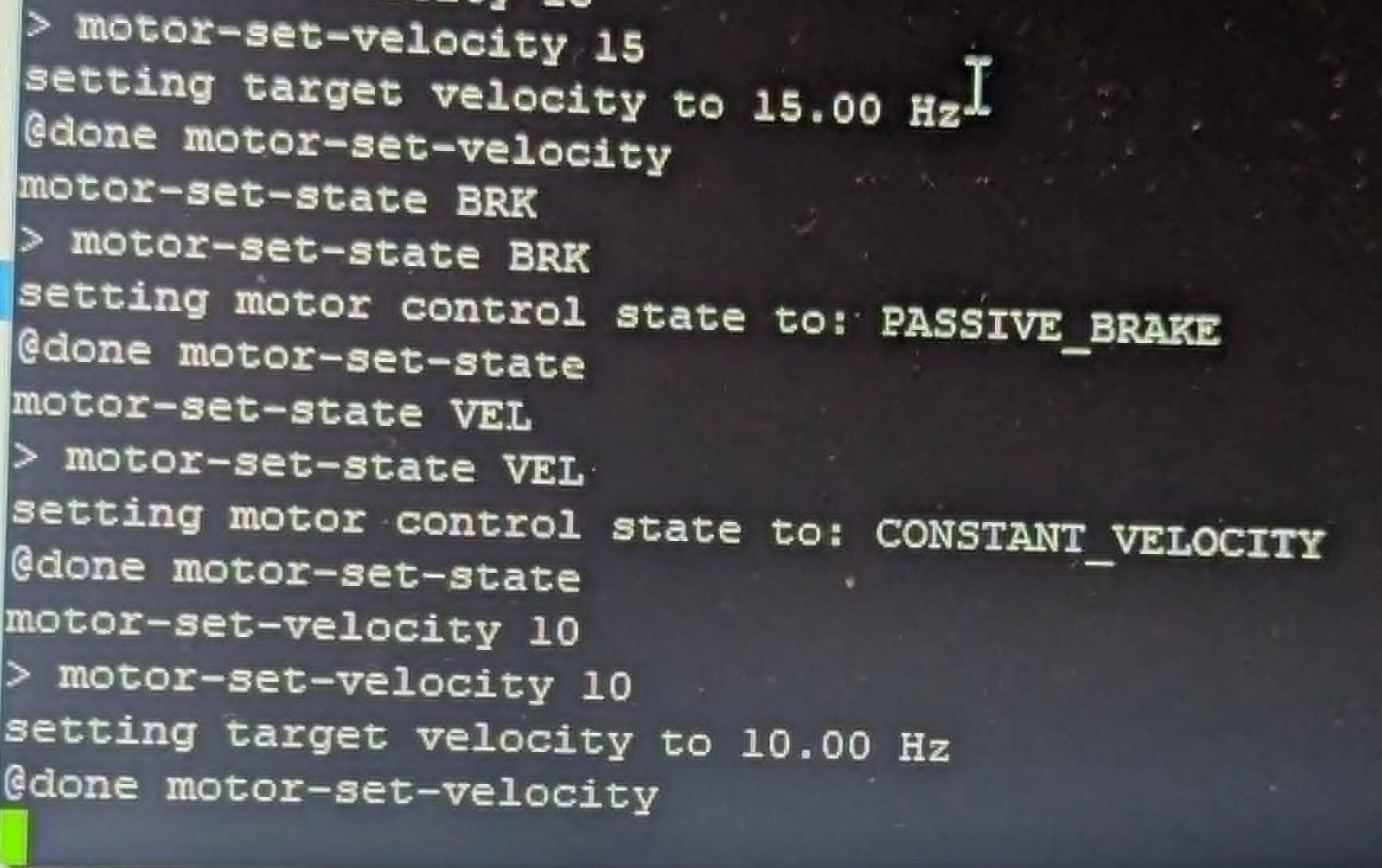
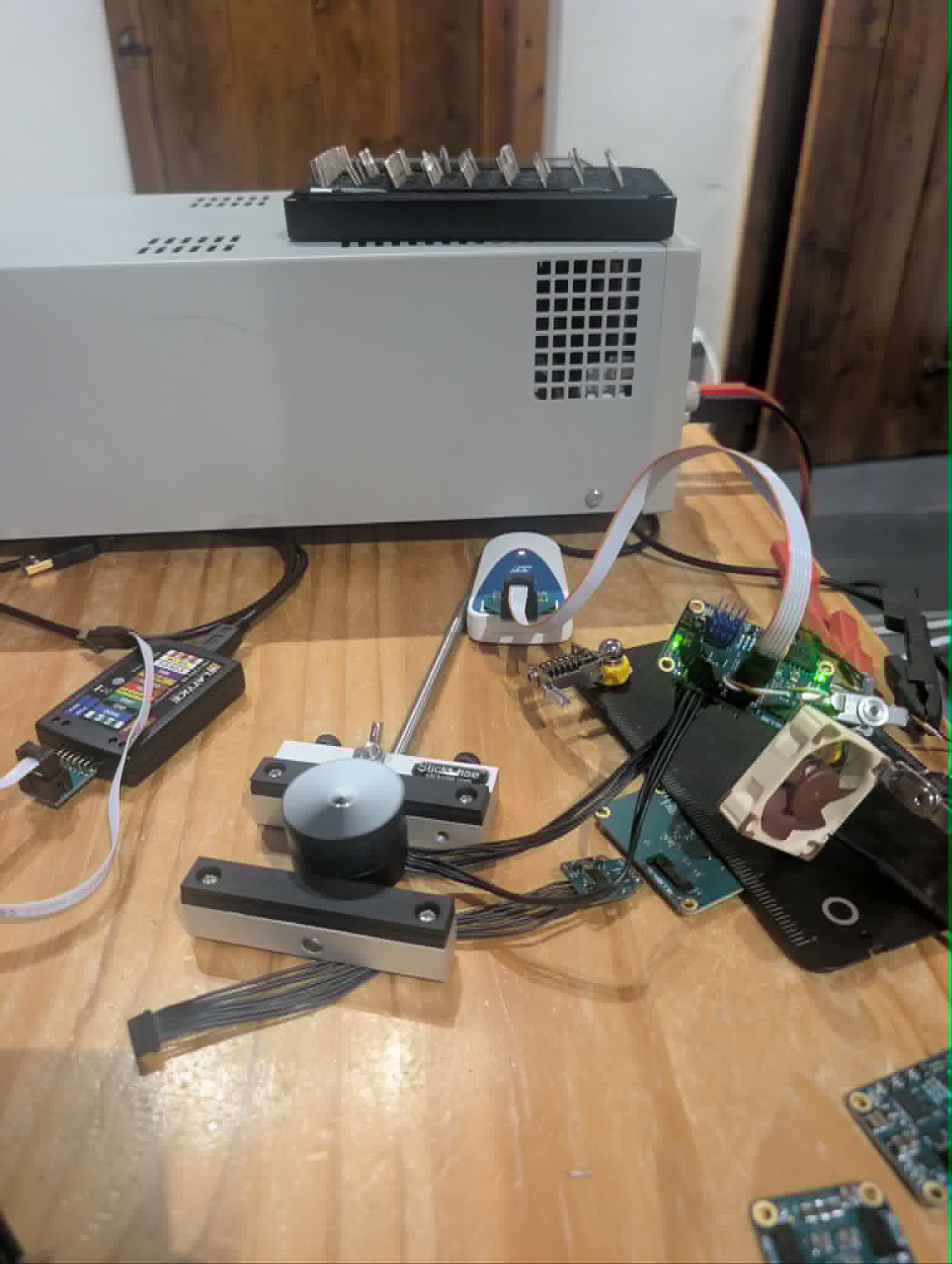
A selection of debug commands, and a motion-blurred spinning motor
Motor spinning with the new hardware (in slow motion)
Motor Driver Beltbox Integration Test
The logical next step was to install the motor, encoder, driver, and cabling into a Beltbox and give the whole lot a run. So this is going to be a bit of a spolier for some of Henry's work but that's his own fault really and there's no easy way of showing the great success here without giving a little bit away.
With the added load (which adds a bit of inertia to the system and helps with the velocity control badly oscillating around the set point) we were able to get some reasonably slow speed driving at a nice consistent rate:
This was running at around 2Hz/120rpm input (motor) speed, which correlates to something like 30 or 35 rpm on the output side after the gearbox. I have evidence of it getting up to at least 15Hz, but I'm pretty sure I got it up to 20 or 25Hz? I'll need to check at some point once things are in a slightly better state, but it was definitely hitting my artificial current limits so I should probably increase them to something a bit more ambitious but the current target for motor speed is something like 35-40Hz (although that would ideally be under a reasonable load).
Most importantly, everything seems to be working pretty smoothly now, and even better - after running it for a bunch, cranking up the speed, and trying to stall it, there were absolutely no FPGA-encoder read errors. Big win for the new hardware there, and down the priority queue the improved error handling goes...
One thing you might have noticed in the second clip is that it sounds a bit rumbly - some investigation & testing to do there but our primary suspect at the moment is the quality of the 3D printed timing belt pulleys due to coarse layer lines & some poorly placed layer transition joints. We (Henry) will play around with some options and hopefully come back with a fix for that shortly.
STM FPGA SPI
Time to start working on some optimisation - I was going to put this off for a bit since properly profiling the various elements of the control loop would be a little fiddly before Claude identified an obvious bottleneck - the blocking STM-FPGA SPI transactions that are running twice per loop (reading encoder position and writing PWM duty cycles) which are currently running at ~1.31Mbps.
I had a go at bumping it up to ~10.5Mpbs (8x increase) but that caused a bunch of CRC errors - I think I might need to bump up the FPGA clock for that as it's currently running at ~44MHz but needs at least two clocks per bit and then it has a couple of metastability synchronisation cycles too. Back down to ~5.25Mbps (4x increase over original) and there were no errors being churned out an I was able to crank the motor control loop rate up to 10kHz!!
There are plenty of other areas for optimisation later down the line that I'm already aware of (although I'm not certain exactly which of these I should be prioritising), but I'll stop here for now an come back later when I start running into more issues. As they say, premature optimisation is the root of all evil.
Lords of the Flies
So that's about it for the technical progress on day 2, but it wasn't all that went on. If the theme last time was king of the slugs, this time it was lord of the flies. I eluded earlier to the local fly population, and as we settled in for a big day of progress the situation properly dawned on us.
We found the raid fly killer a day late but boy did we get some good use out of it as well as the as the UV bug zapper. By the end of the day we were even setting traps, putting food in front of the zapper to attract them before shooing them into it. There's something slightly unsettling about working on electronics with a zapper occasionally going off in the background, but by the end of the weekend we were pretty tone deaf to it (unless it got to the point that a fly got properly stuck on the contacts and the smell of fly smoke filled the living room). I'd place our final kill count somewhere between 75 & 125. I wish I had some pictures to show the scale of the war we waged, but alas not.
There were a lot of fly references that cropped up, with themes appearing in at least 4 of the films we had on in the background, as well as having "dead fly" (fruit shortcake) biscuits in our arsenal of snacks.
But enough about that, onto day 3!
Day 3
A CAN-Do Attitude
So with everything going so well on the motor control & integration yeterday, my focus was on getting the CAN communication working. This has been a long time coming, like 2-3 years long. The original motor driver and pi "helmet" we used in PiWars 2024 had CAN transceivers but we ran out of time to implement anything proper and reverted to using the debug UART connection. It's been included on all of the board revisions since and I even created a file for the implementation and started writing a blog post about CAN over 20 months ago. That's still in draft, and hopefully will be released before it reaches age 2.
With that in mind, I don't want to go into too much detail here since this is already a pretty long update and I want to leave a decent amount to talk about in the post about CAN. Beyond that, while this section is going to be on the shorter side, there was a lot of good progress on the architecture side, such as designing the message ID structure, message types, and more. So lots of infrastructure determined, but not much to show for it right now.
Beyond the less tangible architecture work, I did achieve a key milestone on the CAN front - with internal loopback mode enabled I managed to get CAN communications pinging away at a set rate (in a new CAN task) which would then be received and logged over the debug UART - perhaps not much to look at below but this was a pretty big moment for us as we move to a proper communication protocol which is robust, modular, & scalable.
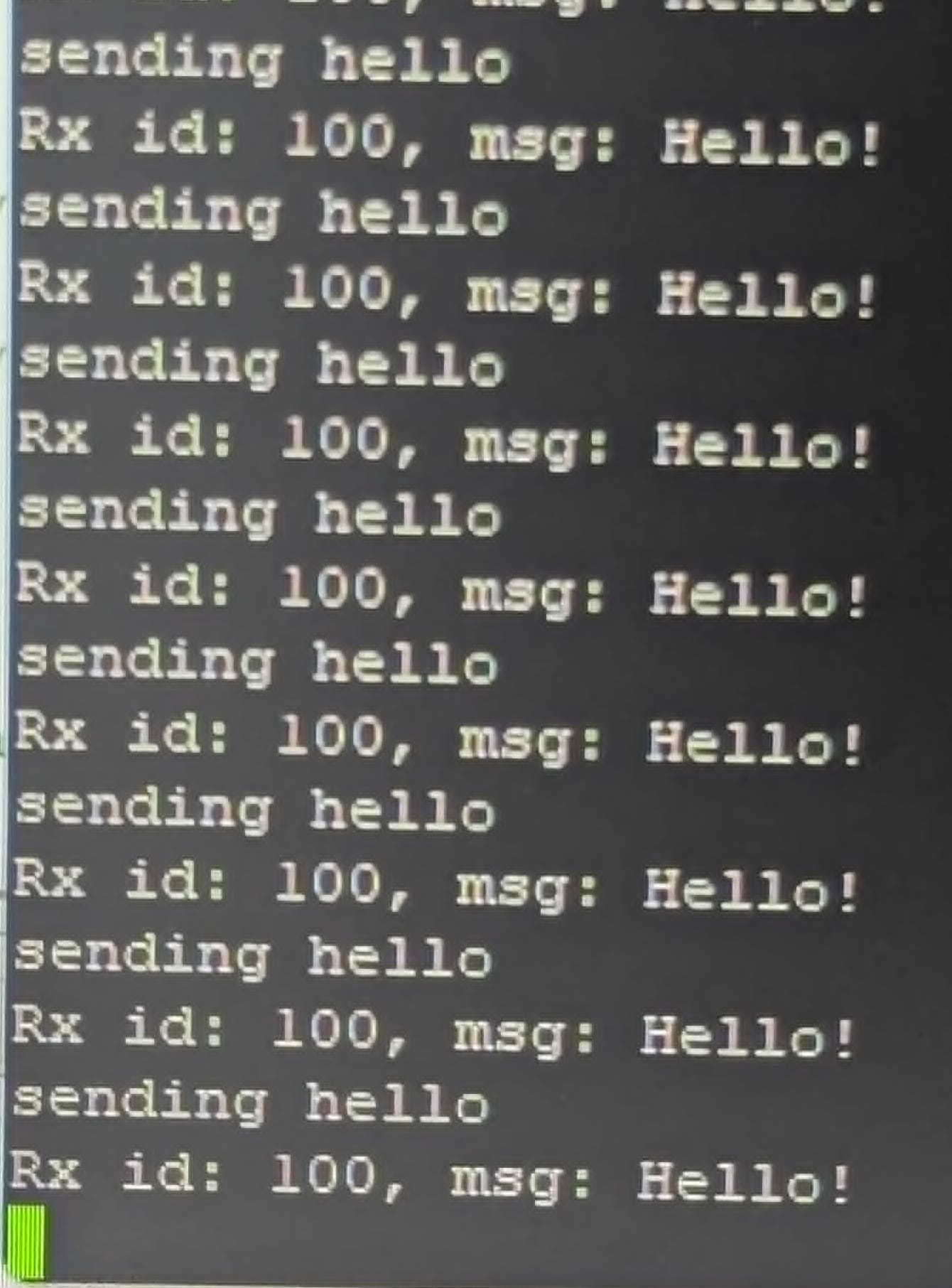
It'll take a bit of time yet to get there fully, but being able to send arbitrary message types that can be easily interpreted without conflicting with each other (as well as having a pretty good max data rate) will open some pretty big doors for configuration & tuning later down the line.
Other Activities
We took a small break on the Sunday after a morning of strong progress off the back of such a great day prior, and took a walk around the Christmas tree farm:
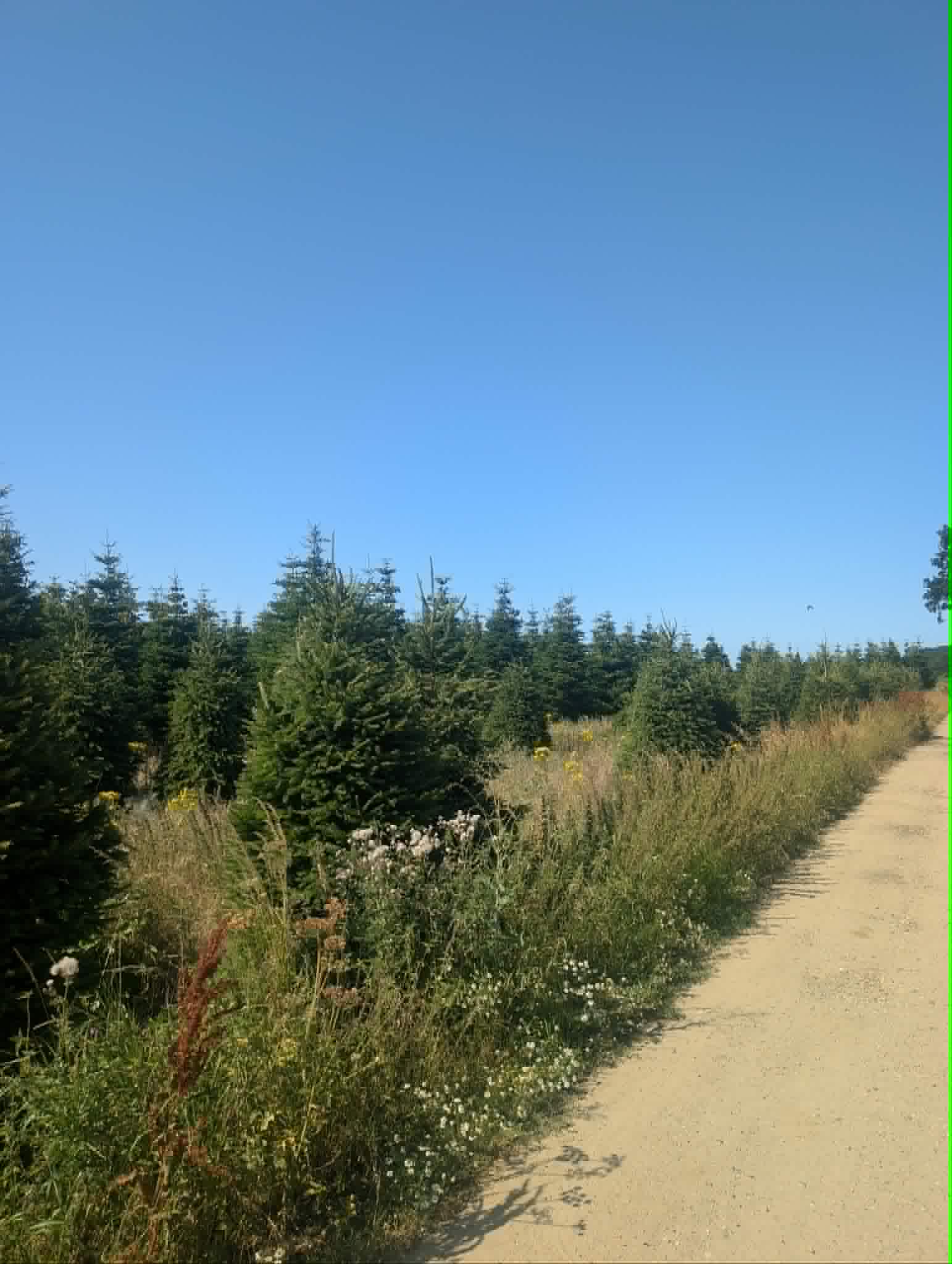
There's something very surreal about going for a walk in the summer heat among a forest of pine trees, but it was a nice break from the hard work and we did some good planning while we walked.
Comments From Henry:
They say never do a bad job well. Here we are only 9 months from the last reatreat and following some suspiciously kind reviews, Max has been asking me to add my infamous retreat comments again. Unfortunately he seems to have done a relatively good job of covering all the points, including a clever name for the flies theme (ugh) which leaves me little to work with.
Max's memory of the amount of progress we made is pretty accurate, it felt like we were both firing on all cylinders and "locked in" as the kids say. The high-level code is really coming together but currently all there is to show for it is a few sneak peeks which will will hopefully temper the excitement for now. Amusingly, I think the most progress Max made was in the run up to the retreat, so maybe I just need to find a load of zero cancellation fee Airbnb's, let him make a tonne of progress and then cancel last minute!
I didn't think this would happen, but I think Max's comments about my blog post frequency might finally be getting to me as I'm feeling a slither of motivation to write some blog posts, although I've said that before, so...
What's Next
We've heard rumours on the grapevine that there might be a Piwars 2027. Now this is early days and nothing is certain, but if true then that once again gives us an immovable deadline on the horizon. This is probably a good time for us now - not too soon that we'll end up in the same position as last time with too much ambition and not enough time, but also with a good amount left to do in the run-up that will keep the heat on and perhaps prevent us from over-engineering things too badly (as if we haven't already).
Beyond getting hyped for a potential competition next year, there's plenty more work to do. Maturing the CAN bus communications implementation now that we have a baseline functionality and a plan for how it will work will be a big chunk of work in the near future, as well as developing the debug tolling for things like
The Spoiler Zone
OK, I was a little dramatic earlier, and I've decided to spill some of the beans on some pieces of Henry's progress - but only if you want to see it.
It is pretty cool though.
Also I can't hide the media with ease, only plain text (and even that doesn't work on email), so stop scrolling here if you don't want to see any more (although I can't imagine anyone will if they've gotten this far).
Click Here for Highlights of Henry's Progress
Beyond the work on the Beltbox, which has largely sat stagnant for the past 6 or so months awaiting the electronics and embedded software to be ready to put it through its paces, he's made some pretty incredible progress on the high level software.
This is still just a sneak peak rather than a full expose, but we had some pretty great successes with lidar scans from real data being turned into an occupancy map, and then path planning with simulated LiDAR scan data feeding into SLAM (Simultaneous Localisation And Mapping) scan-matching and EKF (Extended Kalman Filter) also using simulated IMU and encoder odometry data.
As always, plenty more work to do, but by the end of the year I now have reasonable confidence that we will have a robot build with all new hardware that can drive around autonomously to get to waypoints while avoiding obstacles which should open wide the possiblities for challenge completion & optimisation.
Last chance
...
This is it
...
The moment you've been waiting for
...
Almost there
...
No turning back now
...
Just one more now
...
Here it is
LiDAR scanning, occupancy grid generation, & map plotting
Simulated LiDAR scanning, SLAM, costmap generation, & path planning