Vector Robotics 2027 Retreat - Prep
Hopefully we make slightly more tangible progress this time?


It's that time of year again!
By which I mean that it's not at all the same time of year as last time but I, for one, am itching to make a solid burst of progress and we've managed to find a weekend where we're both free.
As I write this (or rather, began writing this) we're about a month or so out, and the frantic but slightly sporadic prep work has begun to ensure that we have a decent chunk of work that we'll be able to grind through over the course of 2-3 days.
The more astute readers may have noticed the sheer cliff upon which the blog post rate has dropped off - hopefully this marks a brief albeit slightly inconsistent return to form over the next couple of months, before things go back to non-existent again while I'm busy with work again, and Henry remains deathly afraid of making a follow-up to his debut post.
Enough of all this waffle, let's get into the meat of what I've been up to, completely ignoring all of Henry's progress (and side projects).
Current Sensor Testing
We've been slightly skeptical about the accuracy of the current sensors on the motor controller - even after fixing the scaling factor and performing some rudimentary level of calibration. the main thing that's been setting off alarm bells is that there have been a handful of times when setting the target average quadrature current seems to be achieved while only drawing a fraction of said current from the power supply.
I have some theories about why this could be happening that isnt a fundamental issue with the current sensors themselves - more on that later - but for now I was about to order a hefty amount of boards so that we have the hardware to maybe do a full motor drive test over the retreat. This is not a cheap order and so Henry made the very sensible suggestion that we should do a quick test to make sure that we don't want to completely change current sensor beforehand.
Dummy Load
The way we decided to go about this was making a dummy load that we could drive current into with the following key differences compared to the motor that we've been driving up to now:
- No moving parts to worry about
- No inductance (in some ways this makes it a non-ideal dummy motor load, but for now it's kinda nice, and either way it's much easier & cheaper to build)
- A much higher power rating - so no concerns about blowing it up if the control loop goes a bit skewiff
- Easy probing points for measuring various voltages and current flows
So with all that said, here it is:
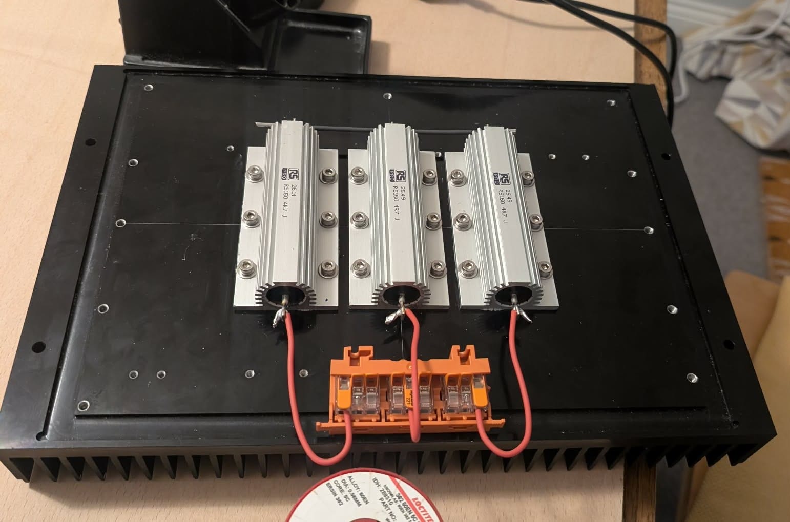
So it's a little over-specced...
But it should last, and it's nice to spend a bit of time/thought/money on some test kit that is for more than just one hacked together test. Hopefully this won't be the last you hear or see of it.
Onto the actual test!
Test Method & Results
Don't get carried away with the connotations of the heading - while it implies a strong foundation in the scientific method, I'd say the testing process is better described as following a faint inspiration of science with a firm helping of FAFO (like most of what we do).
So the test setup was with a motor driver connected into the newly created dummy load (albeit with a motor still hanging on by the encoder), and then driving a constant PWM into the load (for a constant average current). I then used my fanciest multimeter to probe the voltage drop across the (roughly) known resistances to get the current flow through the resistor after a simple calculation which could then be compared against the current measured by the driver sensors.
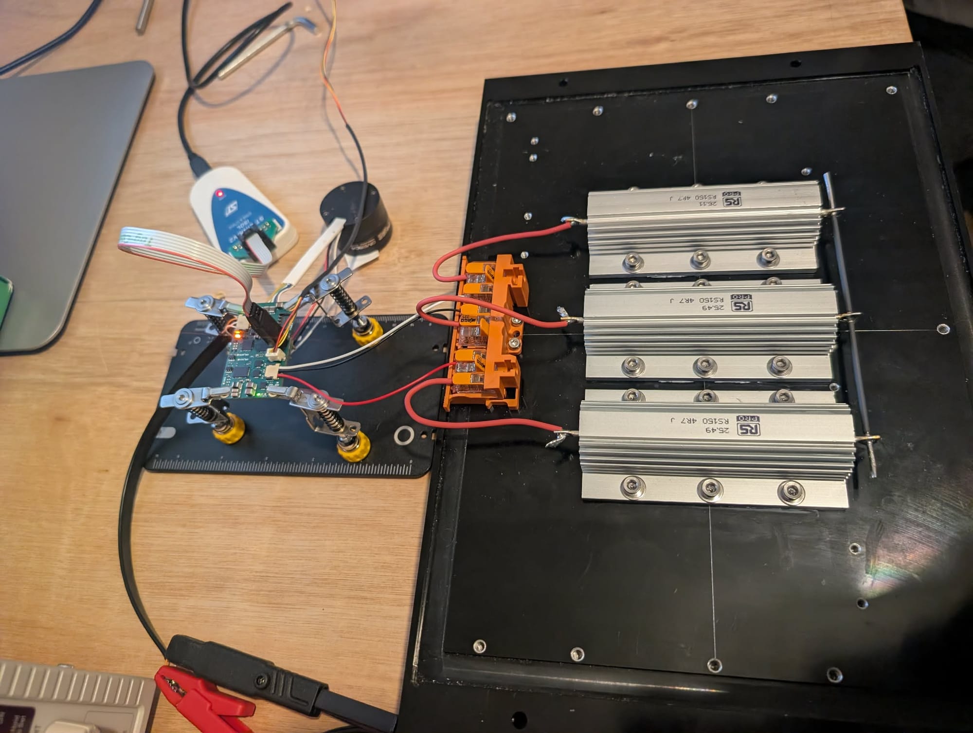
So we ran the test, ran the numbers, and determined that everything looked... fine - I can't remember now what the discrepancy was (and I neither wrote it down or can be bothered to re-do the test) but it was pretty damn close considering a few tolerances here and there.
So what's the cause of the strange readings that caused us to worry that there was a problem in the first place? Well here are a handful of my theories:
- Buck regulator effect - so I think this is my leading suspect with what could cause a much higher motor current compared to the measured input current and yet not show the same behaviour with a resistive load. Effectively the motor windings are acting like the inductor of a buck converter with the driver acting as the switch and diode - this feels relatively plausible to me and would mean that I shouldn't worry about it (wouldn't that be nice)
- Sampling artifacts and/or filtering issues? - this isn't my favourite theory, but is certainly very possible - the sampling of the current sensors isn't the best and I could picture a scenario where the resistive constant load would give solid measurements but due to the effects of the winding inductance or the motor rotation causing changing phase current modulation by the control loop (as intended) interacting in some way with my filtering or sampling rate of the analog sensor output voltage. This would need fixing, but at least should be a simple assembly change to passive components or, if I'm lucky, "just" a software change - the downside is that determining what these changes should be exactly might be quite fiddly (at least with the current experience & data I have) - this probably motivates getting some proper debug logging working so that I can graph data in real time at reasonable data rates which means sorting out CAN.
- Other - there is of course the very real chance that there's something else I've not anticipated that is causing this. I'll cross that bridge when I get to it I suppose.
Either way the result is that, with the impending retreat data rapidly closing, we decided that we had enough confidence in this (and as a whole the latest working copy of the motor driver and encoder designs) that it was worth pulling the trigger on a few more of these so that we can begin to play around with them in their intended final form.
Worst-case we'll be doing very minor filter changes to them, but the value of having a full set of motor drivers fully outweighs that relatively small risk.
New Board Revisions
Let's take a look at what exactly the "final form" (famous last words) of the motor encoder and the motor driver are that I've now got in fabrication again.
Ignoring very minor tweaks, and some effectively useless design output drawing improvements, the updates are as follows:
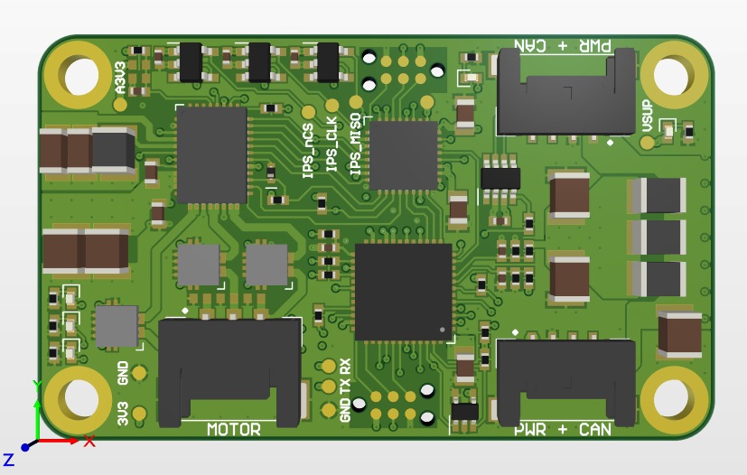
Motor Driver
- New connectors (all Molex pico-lock)
- New encoder interface (no MOSI, differential chip select)
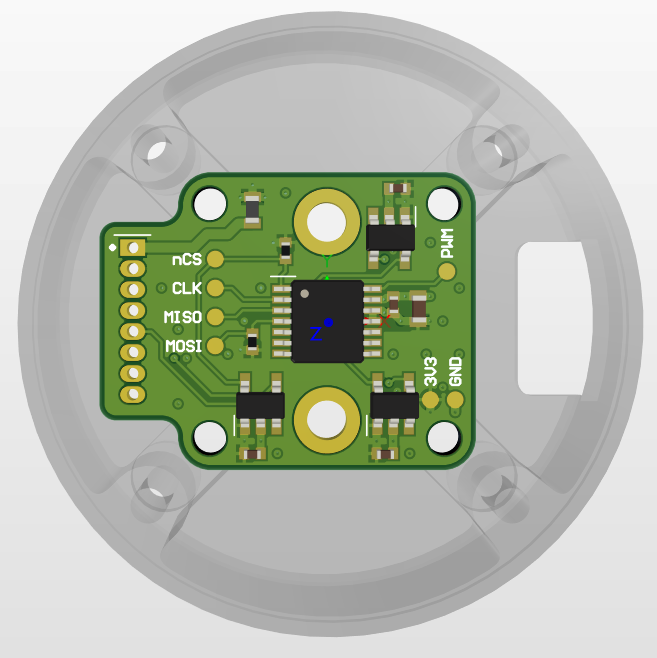
Motor Encoder
- Fixed MOSI default bug (tied high rather than low now)
- New encoder interface (as above)
- New connector (1.27mm pitch through hole pads)
Maybe this doesn't sound like much, but this is the first time I think I'll have been completely happy with the connector choices on a board. I suppose there's still time for that to change though...
Crucially, this is the first time I've had pretty good confidence overall in the designs and therefore I've committed to some pretty large quantities, relative to my prior runs at least, with a full set of each to be assembled (more on that to follow).
Outsourced Assembly
It doesn't feel long since I wrote a post about upgrading my PCB assembly setup and I've made another upgrade - albeit this time in mindset/budget rather than in hardware.
Perhaps it's clear from the severe drop-off in regularity of posts, but I've been pretty busy recently and this has gone some way to motivating a increase in my perceived value of my time. As such I've decided to get my personal project boards assembled by a third party for the first time.
This was a relatively painless process - one evening was all it took to upgrade my Altium outjob files to include files for a BoM and pick & place data, and then a further evening to put all of the required LCSC part numbers into my component library.
There's a small amount of work after uploading the files to sort out the BoM choices (mostly where there are stock issues of generic parts) and to get the component rotations correct, but compared to the grief of fixing assembly related issues of my own making it's a world of difference. Of course there is a very real chance that I get the same exact same assembly issues from them anyway, but at a minimum it saves me the initial assembly time. Realistically though, there's no chance it's as bad as my previous attempts, and a there's a good chance everything just works off the bat! Famous last words again?
Anyway, the costs (including shipping, but not yet including customs...) come to £71.02 per motor driver & £14.53 per encoder (at quantities of 5x and 10x respectively). It feels pretty bad as a lump sum, but at individual quantities it doesn't feel too bad? Does have to be said that my perception of acceptable electronics budget for something like this has gone up significantly over the past 5 or so years - Back then I probably would have winced at even 10% of that...
Fingers crossed I haven't made any stupid errors on these, but I'm fairly confident given the low-risk nature of these updates. Famous last words - hat-trick!
What's Next?
Probably not all that much until the retreat - partially because I'm pretty busy and partially because most of what needs doing is software and that excites me less. The main thing I think I'm likely to achieve is a small amount of hardware bring-up on the new boards (which have since been fabricated, assembled, shipped, delivered, and partially tested as I now finish up writing this a couple weeks later) to ensure that they at least sort of work.
Beyond that, I'm hoping to make progress on a handful of tasks such as:
- Debug/fix any random hardware bugs?
- Progressing RTOS development and transfer
- CAN bus communications development
- Test/debug utility/GUI applications?
- Improving motor tuning (post RTOS)
- Improve error handling
- etc. etc.
But you'll have to wait to hear about all of that, so see you in a few weeks with the next update!