Vector Robotics 2025 Retreat - Prep
A summary of the smaller pre-retreat activities & progress


Intro
It's been too long since Pi-Wars (with nothing to change on that front in 2026), so we decided we needed a big event for the vector robotics team to improve morale. We also both had a few days of holiday to burn, so why not.
We were hoping for centerparcs but when it came to book it was a little expensive, especially since we wouldn't exactly be making the most of the pool, so an airbnb with hot tub would have to do instead.
The retreat ran for 4 days, 3 nights but we ended up putting in quite a shift the night before. Half of the first day was spent packing/travelling/unpacking, and the last day was pretty much a complete write-off, so we ended up getting about 3 solid days of work in total. This post will cover the bits and pieces of progress in the month or so up to the retreat, including the night before in particular, and the next will cover the progress we made on the retreat itself.
Plans
Just to set the stage, here are what some of our rough plans were pre-retreat:
- Get the ReV-B motor driver working
- Get full FOC motor control working (with calibration saved as EEPROM settings)
- Torque testing on a single belt-box (Yes the belt-box exists already, Henry is approximately 1yr behind on blog posts...)
- Simple CAN comms working
- 2 (or 4?) motors driving together for a proof-of-concept mecannum wheels drive
- EKF tuning (more about that in post from Henry at some point?)
So lots to get prepped to allow everything there to be smoothly integrated then.
Progress Until Night-Before
New Pi "Helmet"
Previous post about the design of this, I won't recap it here.
Encoder Errors
I mentioned in a post a while back that I was getting some signal integrity issues with the motor encoder readings when the motor was being driven at the same time.
I did some investigation and found the the data signal returning from the encoder board was very weak (even without the motor being driven). I don't have very good pictures for this because I was in a bit of a rush, but below you can see the relatively clean bursts on the clock signal to the encoder and the fairly rough looking return data with pulses even appearing inbetween reads:
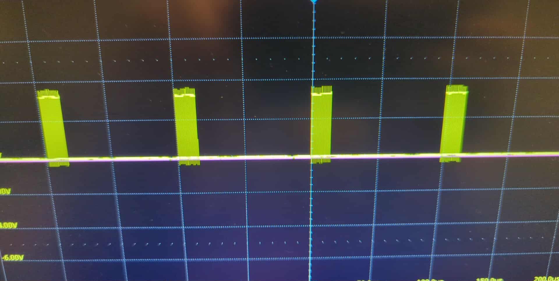
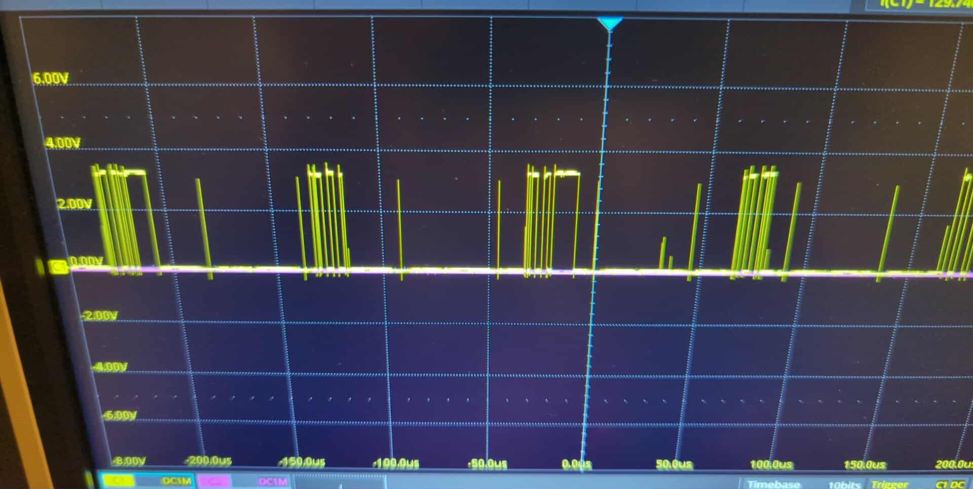
Left: bursts of pulses on the clock signal for each packet read, Right: data return signal showing noise between packet reads
After opening up the back of the motor and inspecting the encoder board I found a loose wire - frankly it's impressive it was working as well as it was with just one of the differential data wires intact.
This gave me a bunch of confidence in the interface and I was happy to pull the trigger on buying RevB of the motor encoder & driver boards.
Settings Engine
This is something that I've been in dire need of for some time (since last PiWars really). Previously, I had been putting calibration constants into the code before compilation, which I would then flash onto the board. This was barely acceptable before when I'd only ever be working on a single motor driver board at a time, although even still I'd have to recomple and reflash if I changed motor encoders.
One way of fixing this would be to send these at boot (from the Pi for example). This would mean that the motor drivers don't need any memory of custom settings, however it leaves room for error, pairing the wrong settings with each board (particularly as modular parts get swapped around).
I've decided to go down the route of storing calibration data and other settings on each motor driver, which also has the additional benefit that running submodules on their own just works (without cal data needing to be sent at each boot). I'm using an EEPROM connected to the STM microcontroller for this storage - the STM has plenty of internal non-volatile flash which could be used for the same job but I don't want to mess around with flash management on the STM just yet. Maybe after I've sorted out a CAN bootloader partition I'll look at integrating the settings storage, but even then I might not since this means that an accidental full-chip erase of the STM won't delete the saved calibration data in the external EEPROM.
Unfortunately there's no screenshots of console output for this now since it's all untested at this point, but it promises to be a great quality-of-life improvement for me while developing. I'll talk more another time about the specifics of the settings engine that I've written, how it works, and what I've included so far.
Motor Control Code Refactor
Another thing that's been on the horizon for a little while - I refactored the flow of the motor control update loop. I don't think this is super interesting so the highlights are:
- Implemented nested PID loops for velocity and position around the torque control loop.
- Implemented states for the various motor control modes (position, velocity, torque, user PWM, passive brake, disabled).
- Improved data handling and motor control mode state change handling so that it doesn't go crazy.
I hadn't fixed the encoder board on my current motor driver, so all of this was also completely untested at this point. What could possibly go wrong?
CAN Communications
This will be a short section - I had planned to throw some code together so that we could start working with more than one motor driver at a time (which is the limit with the current UART comms setup) but this never really happened.
TLDR: no change on the CAN front
New Hardware Assembly
So I'd received boards back for the first revision of the CAN + Power Pi Helmet, and the second revisions of both of the CAN motor driver and motor encoder boards. Now to assemble them - should be easy now that I have stencils.
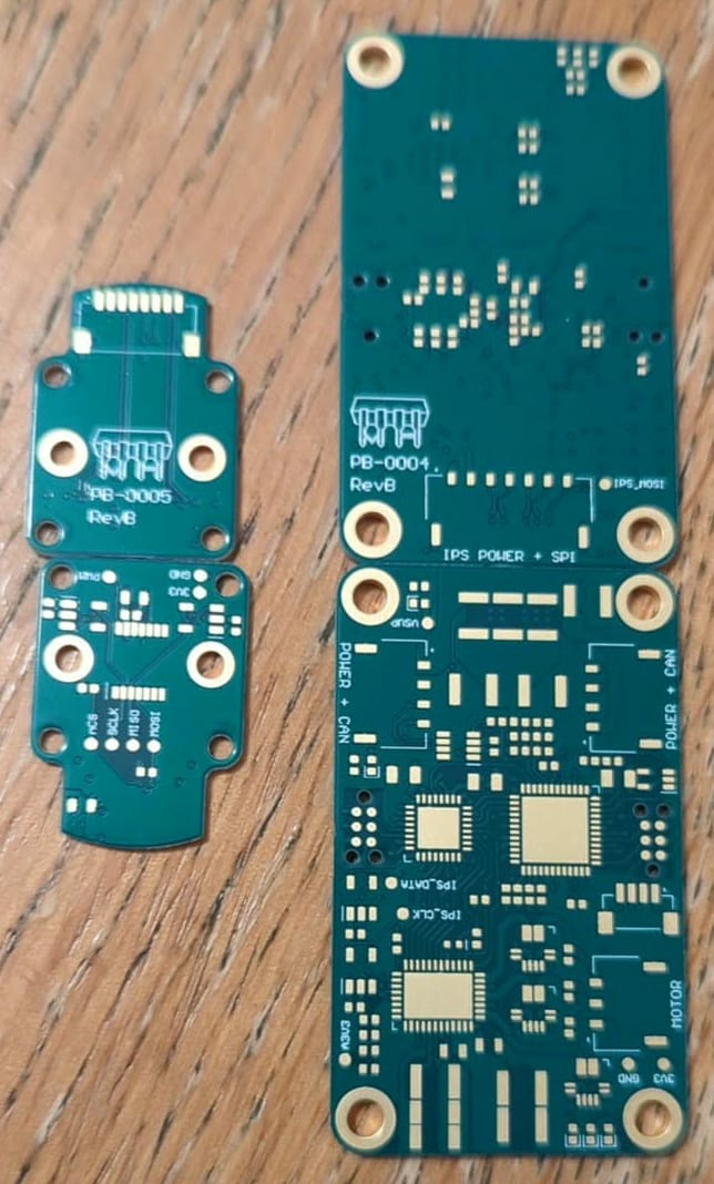
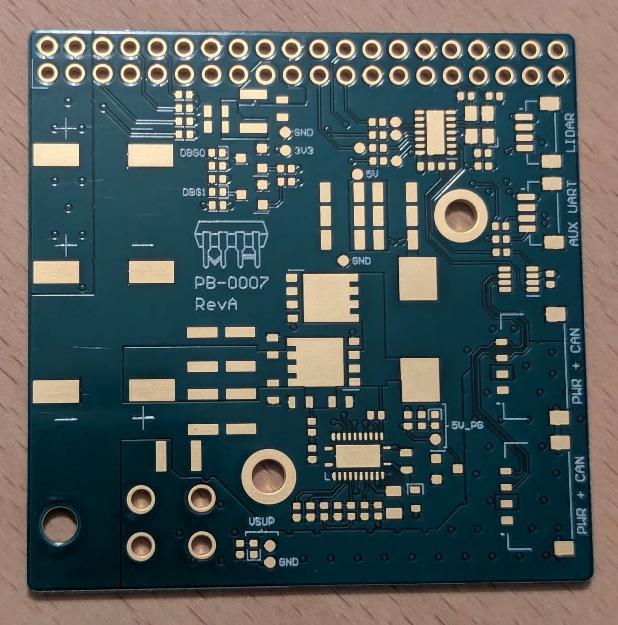
Bare boards for the new PCBA revisions
50/50 - the assembly was much quicker than without stencils and the capillary action of the solder paste does a great job of neatening up my placement, but there were plenty of dry or bridged joints that needed sorting.
After sorting these as best I could and powering on the Pi Helmet it didn't do anything. Tried the same with the motor driver and got a very similar result. We would've tried the encoder board but we can't easily test it without a motor driver. So begins the arduous debugging process then.
So Begins The Hardwars Debugging
Lets start with the Pi Helmet - the power supply wasn't doing anything, literally nothing. The obvious candidate would be the buck controller IC - either faulty or a short underneath - so I swapped it out. This time some life, but still not quite right - the power-good LED came on, but the output voltage was about 3.2V rather than the target 5V (which means the power-good LED really shouldn't be on...), but at this point we ran out of time to debug and pushed properly fixing it back to the retreat-proper.
Next the investigation into the motor driver's problems and, funnily enough, it was having power supply issues too. The motor driver IC wasn't booting up the 3V3 supply similarly to before. Jump starting it didn't work, but providing it an external 3V3 supply allowed programming of the STM - but not the FPGA, for whatever reason the JTAG interface wasn't happy. Again, that's about all we had time to determine, so we'd have to sort everything else during the retreat as well.
The Retreat
You'll have to wait a week or two to find out how things went over the retreat and what we did (or didn't) get working, but it's pretty safe to say that we didn't go into it with particularly high hopes - our plans were banking on having all new boards fully working (multiple copies of which for the motor driver) but instead we only had a single very broken copy of each. We were also hoping to have plenty more software working which was in most cases untested (or completely unwritten).
No shortage of work to do though at least.