CAN + Power Pi Helmet
Not to be confused with a Pi HAT...

Intro
So, we're going back in time a bit for this one, but it's finally time to talk about the Raspberry Pi Helmet that I've re-designed for this iteration of the robot.
It's been a long time coming - so long in fact that my first commit on the project was nearly a year ago now (7th of Jan), although a lot of the work around then was largely a copy and paste job from the previous Pi expansion board from our Pi-Wars 2024 entry.
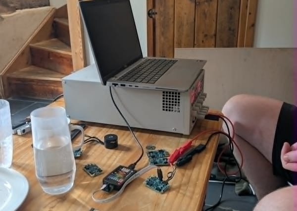
I then proceeded to get distracted with motor control for many months, and so the bulk of the work on this board properly happened around the middle of November in my mad panicked rush to have hardware ready for integration testing during the Vector Robotics 2025 retreat (including paying an extortionate amount for expedited shipping).
So, lets get into the details of what I designed and, more importantly, ordered!
Pi Helmet Functionality
The first thing to note is that this is a Pi Helmet & not a Pi HAT - there are many requirements that I have blatantly ignored that would disqualify it from the official spec(s) - Raspberry Pi HAT Repository & Raspberry Pi HAT+ Specification - more on those concessions/omissions later.
Not to say it's not complicated, but the Pi Helmet I've made isn't far off a glorified 5V buck (step-down) regulator power supply. Its key purpose in life is 2 things:
- Take power from the 6s (~24V) battery and convert it to a nice clean & stable 5V supply for the Pi so that we don't require another battery (or have to use yucky non-latching USB for power)
- Provide CAN-bus (and power) connections for the modular motor driver board, and any other nodes we might want to put on the CAN bus
While these are the most important functions for the Helmet, there are a few other functions that are desirable to provide additional functionality such as:
- LiDAR UART
- Auxiliary UART
- IMU/auxiliary I2C
- Fan control
- LED control
- Debug/indicator LEDs
I think most of these are fairly self explanatory so I won't go into any detail on those. Most of this is just breaking out existing functionality onto specific connectors, so feel free to google things if you're lost.
What's New?
In all honesty, not that much.
The old board had a 5V power supply, a CAN controller & transceiver, 2x UART headers, 1x I2C header, an LED control header, & debug LEDs, so on paper it's basically just a fan header that I've added.
There are however some very important changes that are worth discussing.
The first issue that plagued the previous version has some pretty serious issues with the 5V supply stability/ripple/brownout. Essentially, with the LiDAR plugged in and the WiFi connected we were seeing some warnings from the Pi saying that it was throttling the CPU to prevent power issues. This is obviously not ideal, even less so when we disabled this behaviour and started seeing some instability with various functionality like the WiFi. Anyway, I've improved the layout significantly (for the high frequency) and added some big electrolytic capacitors (for the low frequency) this time so it should be absolutely fine now!
CAN speed wasn't an issue with the last board like power was (since it was never used...), but I've improved it anyway. I've changed to the MCP2517FD CAN controller which supports CAN FD (flexible data-rate) up to 8 Mbps (compared to the 1 Mbps of the previous MCP2515) along with some other nice things. I'll do a much more in-depth post about CAN bus when I have some of that running properly so that's enough on that subject for now. A final note - the CAN transceiver on the motor drivers can only go up to 5 Mbps, but that's still a marked improvement over 1 (and the other FD bonuses too) so I'm happy.
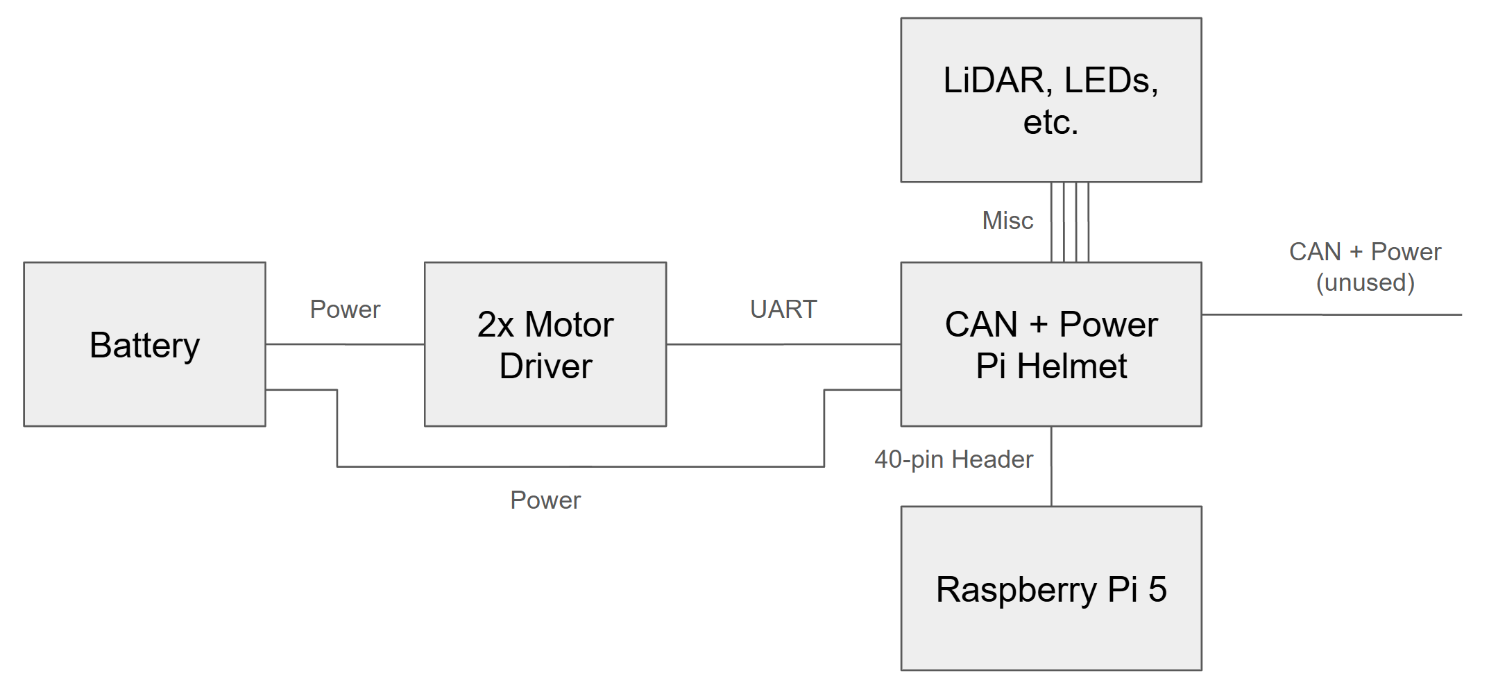
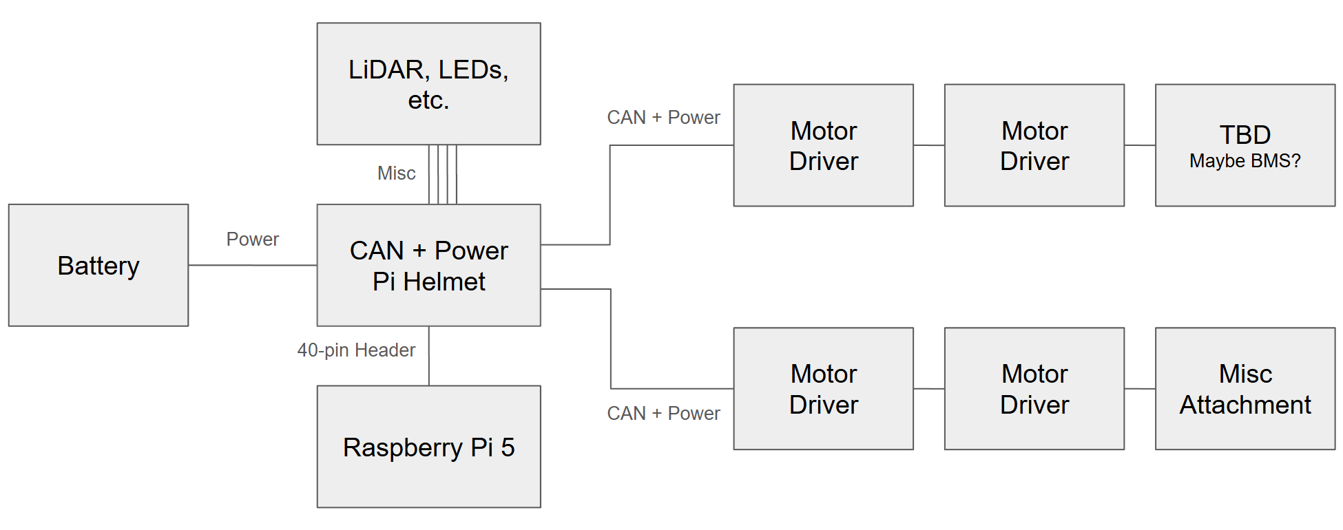
The final big thing I've changed are the connectors for power input due to the new electronics architecture. The old board used to passthrough the power & CAN connections (which it still kinda does) but it also now has the main power input connector which feeds them. Previously this was handled by the motor driver board, but now with 4x modular motor drivers distributed around the system this doesn't make sense. Hopefully this makes sense? If not maybe this ancient post and the additional diagrams below will help: Thoughts about System/Electronics Architecture
A (not-so) Quick Tangential Rant
I have a bone to pick with the Raspberry Pi 5 - more specifically its documentation - the information about the 40-pin header functionality is absolutely dire.
The thing that makes this absolutely crazy to me is that this isn't something Raspberry Pi should be hiding - they've added a bunch of functionality, they should be screaming from the rooftop about everything it can now do on this interface that the old models couldn't. Not even is it not well advertised though, but I genuinely wasn't even sure if the one document that I found had correct information until I actually got the board back and tested it. Even now I'm not convinced I've got the full pinout table correct.
Starting with the product page on the supplier's website (PiHut) gives plenty of links to documentation and several paragraphs of descriptions, but nothing of great detail about the 40-pin GPIO header. Two linked documents with potential (albeit low) for containing this info are the announcement and the product brief, but neither contain anything significant about the header.
Over to the Raspberry Pi website then to get some more detailed documentation - starting with the GPIO documentation section, which onyl contains a very simplistic diagram showing where power, GPIO, and EEPROM I2C connections are. Further down in Alternative Functions there's a pinout description for a few other functions, but nothing on the level of what the Pi 5 can do (and also no diagram 😠). It also mentions the pinout command of the GPIO Zero Library which then links to pinout.xyz/. A nicely formatted pinout diagram with dynamic information based on the selected pin/peripheral!!
side-rant: I can't believe that there are 3 different numbering systems for the Pi's GPIO - physical, BCM, & WiringPi. Two systems (say, physical and logical) are understandable, but the BCM/WiringPi split is just stupid. I think WiringPi numbers are obsolete now but they're still all over the place and probably will be forever 🙃
ok, so back to pinout.xyz/ - clicking on each pin gives a list of functions, or you can select an alternate function type to see the relevant pins - sounds perfect! Well I thought so at first, but there are a few issues from my perspective - it only has SPI0, SPI1, I2C0, & EEPROM I2C peripherals listed - there are plenty more of those available on the Pi 5. On the UART front it's a little more confused - it gives a bunch of pins for UART TX & RX, but apart from the UART that the other Raspberry Pi documentation showed the others don't say which UART they're for. Clicking on the pins then doesn't even show UART functionality at all. Also, it gives two JTAG options which feels wrong, maybe that's correct but I feel like some more info there might go a long way. I'd got about halfway through filling out my own pinout table based on this before I decided I didn't trust it anymore, so back to the Raspberry Pi website.
The Serial Peripheral Interface (SPI) section gives a handful of additional SPI peripheral pin descriptions for the Pi zero, 1, 2, 3, 4, 400, CM1, CM3, & CM4. The Pi-5 & CM5 are notably absent. The Configure UARTs gets as close as anything so far, teasing the Pi-5 for once and listing UART0-4 (interestingly it doesn't list UART10 here but does further on, but that's the least of our problems at the moment). Sounds like a good lead (and confirmation that there are more UARTs than the initial searches would suggest), but no mention here of what pins they are on. And no mention of I2C peripheral pinouts either - the best I can find is Board-specific labels and parameters which only mentions 2 of them anyway.
There's no shortage of third-party sources around that provide the 40-pin Pi GPIO pinout, but as far as I can tell none of them help with the Pi 5 increased 50-pin header functionality. If anything, the relative abundance of these pages actually makes it difficult to find any that document that additional functionality (if they exist at all).
Finally, I ended up scrolling through the RP1 Peripherals I/O chip datasheet (partially just to confirm to myself that it did actually have the extra peripherals I thought it did). You might ask why I didn't look at this earlier - for one it's watermarked as "draft", and secondly I wouldn't expect the I/O chip to, in any way, define where the pins it has would go on the product(s) it's later used on - silly me I guess. Under "3.1.1. Function select" there's the following table:
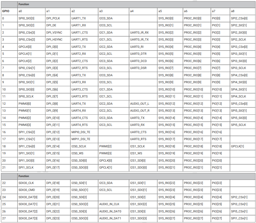
A few minor comments about this table - functions 5-7 could have been shown in a more efficient manner, there's no mention of JTAG here, & the SPI_IO enumerations are thoroughly unhelpful (the SPI section below this table helps for slave instances of the SPI, but not really for master instances).
With a little cross referencing between this table, pinout.xys, & third-party pinout diagrams, I was able to "confirm" that it was likely that the GPIO numbers in this table probably correlated to the BCM pin numbering on the 40-pin Pi header.
So I transcribed the relevant parts of this table (as far as I'm concerned) into my schematic sheet for the header, and converted the SPI data pins to MISO/MOSI (by comparing the SPI0_IO[0] & SPI0_IO[1] of this to the SPI0_MISO & SPI0_MOSI to the other pinouts, and then assuming that the rest of the SPIs used the same convention). As such, we have the following pinout table:
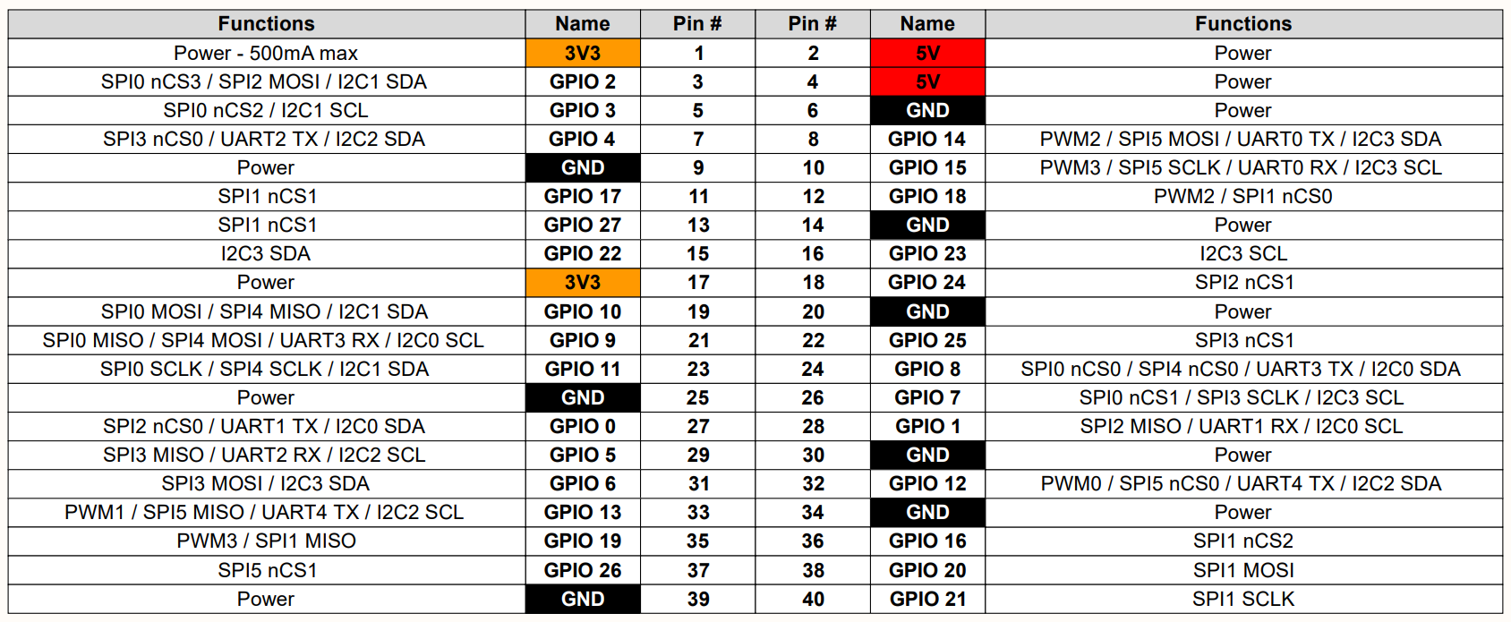
I've sinced combed through the raspberry pi site (without the time pressure of needing to get the board out) I've found this page of datasheets which has some wonderfully useful datasheets for everything (including a great one for the Pi-4 as well as some I/O schematics. The Pi-5? Just a product brief and a step file. It's been on sale for just over 2 years now - even longer since it was first announced!
What a rollercoaster - I shouldn't have to spend this long searching for this info and I shouldn't be so unconfident about it by the end of it.
@RaspberryPi - sort your Pi-5 documentation out.
The Final Design
Here it is in all it's (slightly shameful) glory:
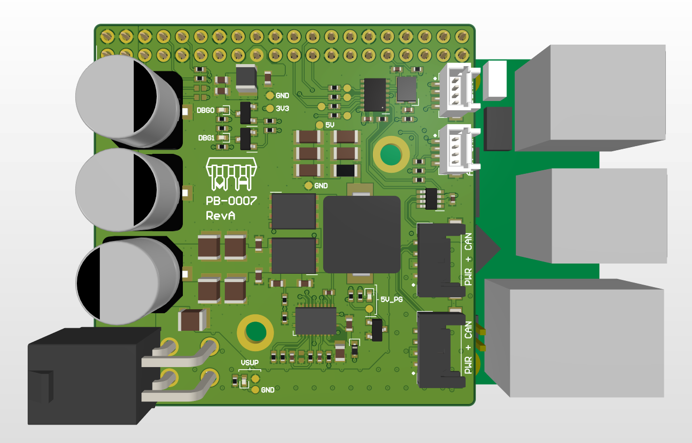
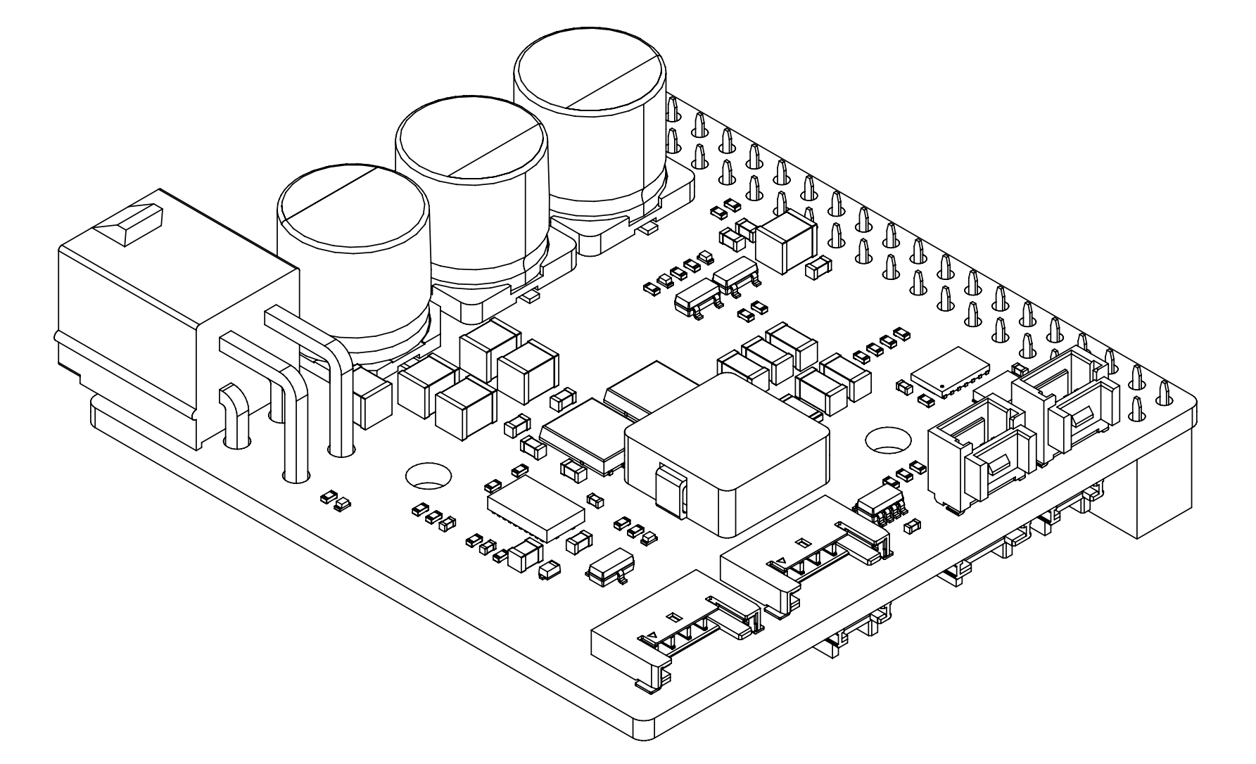
3D Renders of the first revision of the CAN + Power Pi Helmet
To the trained eye, some things may look a little strange about this - the most obvious of which (I think) is the mounting hole locations. What's going on there?
Well, to get the layer count I wanted (>4) at a reasonable price I had to make the board size quite small, specifically 51 x 51 mm. As a bonus though, this size limit gets me 8 layers, filled and capped vias, & ENIG (gold-plated) surface finish, all for just $2. Shame about the $56 expedited shipping fee and $13 customs charge...
Am I proud of what the size limits did to the board? No. Did I continue regardless? Absolutely.
In case you're wondering where the rest of it is, there are a few connectors (but not much else) on the bottom side for the LED control, fan control, & auxiliary I2C.
Not a HAT (or HAT+)
There's a lot that makes the RevA CAN + Power Pi Helmet incompatible with the HAT/HAT+ specification. Where to even begin?
- It partially blocks the camera cables
- The mounting holes don't align with those of the pi
- It doesn't have an EEPROM on board to identify itself (although I have at least left those pins spare)
- It doesn't have any sort of protections on the power supply
I imagine there's a handful of other small problems with it, but at the end of the day it isn't a consumer product (yet), is very application specific, and is unlikely to have anyone completely unfamiliar with the design messing around with it, so who cares?
Maybe one day I'll make a HAT+ compliant version, but for now, long live RevA of the Vector Robotics CAN Pi Helmet!
What's Next?
This is the biggest single chunk of work I did in the run up to the 2025 retreat/hackathon, although there were lots of other little bits and pieces, so I think there'll be one more post summarising the last bits I did in preparation before we get to the main event.
Maybe we'll get a Christmas new-years miracle and Henry will get around to his second post, so that you can see all the other mechanical work that's been going on (I think the beltbox must be at revision 20 or 30 by now), or even the high-level control software that he's been working on for the past year or two...
There's just so much exciting, and in some cases quite depressing, progress to write about. I have 5 articles in draft at the moment, so hopefully the cadence of posts will be a little more regular until we're caught up again!