The Low-Down on Slowing Down
A Mechanical post!? from Henry!?!?!?!


I guess this will be my first post. I'm not quite sure it will read as well as Max's posts do, but I figured at some point one of you readers might like to read about some real engineering (Mechanical of course...), so here we go!
No Brushes, More Power, More Pain?
If you haven't already realised, we really like brushless motors. I'm not really sure where this first came about but if I had to guess it would probably be a combination of only using very cheap brushed motors previously and then, whilst building our first FPV quads, experiencing nicely built and smooth-running brushless motors and realising that was the way forward.
Turns out, there is a reason why most hobbyist robotics projects use brushed DC gearmotors instead of brushless motors, the first of those reasons is that they aren't as easy to control as standard DC motors, just take one look at Max's blog posts to get a feel for that. The second being that there just aren't that many motors that fit the size, speed, cost and torque requirements of what we need for a PiWars robot. We did manage to find some for PiWars 2024, but you don't even want to know how much they cost if bought off the shelf.
For the next competition (whenever it may be!) we decided to aim for something more reasonably priced. There are plenty of brushless motors aimed at use in gimbals, they are readily available and not too expensive. They typically offer lowish speed, decent torque and aren't too physically big. After a few in-depth spreadsheet calculations and much deliberation, the one we eventually decided on was the iPower GM2804 with the encoder. For our Field Oriented Control dreams, a high-resolution encoder is critical (for more info on that you'll have to go and read Max's post on it, it's way too far below my pay-grade to discuss here...). The only mechanical change is that the encoder addition makes the motor bigger and my job of designing a small gearbox type package harder!
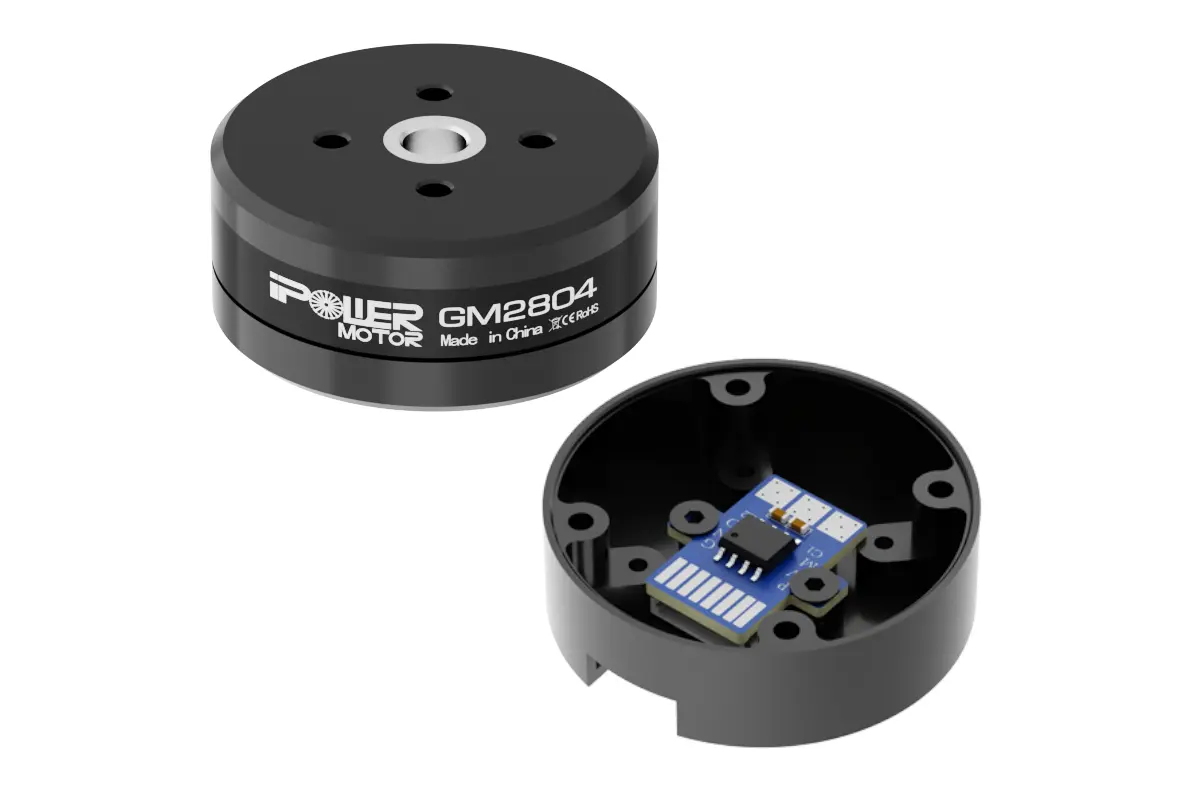
Although the iPower GM2804 is within our price and size budgets, its speed and torque specs don't really meet our needs. From the datasheet, the rated speed is around $1700\,rpm$ @ $10\,v$ supply voltage, that equates to around $170\,kv$ (kv is rpm per volt!). The torque is rated at $250-300\,g.cm$, but to be honest I always take torque numbers with a heavy pinch of salt, especially when looking on the cheaper side of things...
The Need for (slow) Speed
Now, don't get me wrong, $170\,kv$ is A LOT better speed-wise for us compared to most of the other brushless motors on the market in this size (think 1500kv +), but with some quick calculations, its still too fast for our purposes! If we re-used our PiWars 2024 wheels with a diameter of $\approx 100\,mm$, we can calculate the maximum theoretical speed using:
\[v = \omega_{wheel} r_{wheel}\]
where:
$v$ : linear (forward speed) [$m/s$]
$\omega_{wheel}$ : wheel angular velocity [$rad/s$]
$r_{wheel}$ : wheel radius [$m$]
Since $r_{wheel} = \frac{d_{wheel}}{2}$,
\[v =\frac{d_{wheel}}{2}\omega_{wheel}\]
To calculate the forward linear speed in $m/s$, we need to convert the motor speed in $rpm$ to $rads/s$:
\[\omega_{wheel}=RPM \times \frac{2\pi}{60}\]
which substituted into the first equation and simplified gives:
\[v = \frac{\pi d_{wheel}RPM}{60}\]
finally, using our values from above:
\[v = \frac{\pi \times 0.10 \times 1700}{60} = 8.90 \, m/s\]
That means that without any gearing the theoretical top speed of our robot would be $8.9 \, m/s$ and would fly across the pi-noon arena in 0.2s... That might be a little overkill speed wise, and lets not even bother calculating the required torque to accelerate to this speed within a desired time, its easy to do in an excel sheet but I have better things to be doing than writing all the LaTeX expressions out... (I'm a perfectionist don't you know!) Anyhow, its probably way more torque than the motor will be able to provide.
Spin less to win more
Spinning the wheels slower with more torque is the goal here, and there are a lot of methods for doing so. Luckily, physics means that as you add speed reduction by means of gearing, torque increases. This is a linear-relationship in a theoretical world, so if you half the output speed, you double the torque. In the real world that doesnt translate perfectly, some torque is lost to friction.
Each speed reduction method has pros and cons so I'll try to explain the thought process somewhat. With motors within the size category we are using, we want to make maximum torque without reducing the robot's speed to a crawl. The key considerations for choosing the reduction method for the robot are the mechanical efficiency, and manufacturability. Below is a summary of sorts, comparing common speed reduction methods.
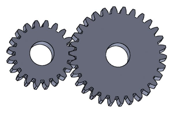
Spur Gears
Spur gears have straight cut teeth, these are probably the gear you are thinking of when you think of a gear... They typically have high efficiency, are compact, give a predictable ratio and are easy to manufacture.
Advantages
- High Efficiency
- Compact
- Easy to manufacture
Disadvantages
- Noisy at high speeds due to sudden tooth engagement (the whole width of the tooth engages at once)
- Moderate load capacity
Helical Gears
Helical gears have teeth which are cut at an angle (helix) to the rotation axis, this leads to a gradual engagement.
Advantages
- Gradual enagement helps lower noise
- Increased load capacity (larger tooth contact area)
Disadvantages
- Generate axial thrust (trying to slide gear along the shaft axis), requiring thrust bearings or excess wear
- Lower efficiency due to sliding friction during tooth engagement.
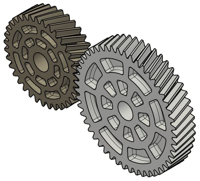
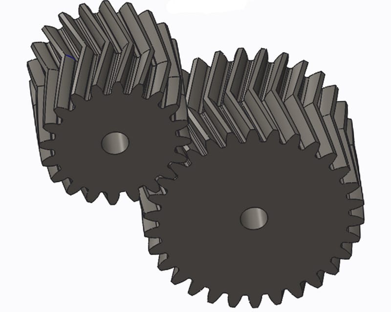
Double Helical Gears (Herringbone)
Take one left-hand and one right-hand helical gear and stick them together, boom, axial thrust problem solved!
Advantages
- Smooth and very quiet
- Very high load capacity
- No axial load on bearings
- Look awesome
Disadvantages
- Very hard to manufacture using traditional methods
- Require precise alignment to ensure good teeth meshing
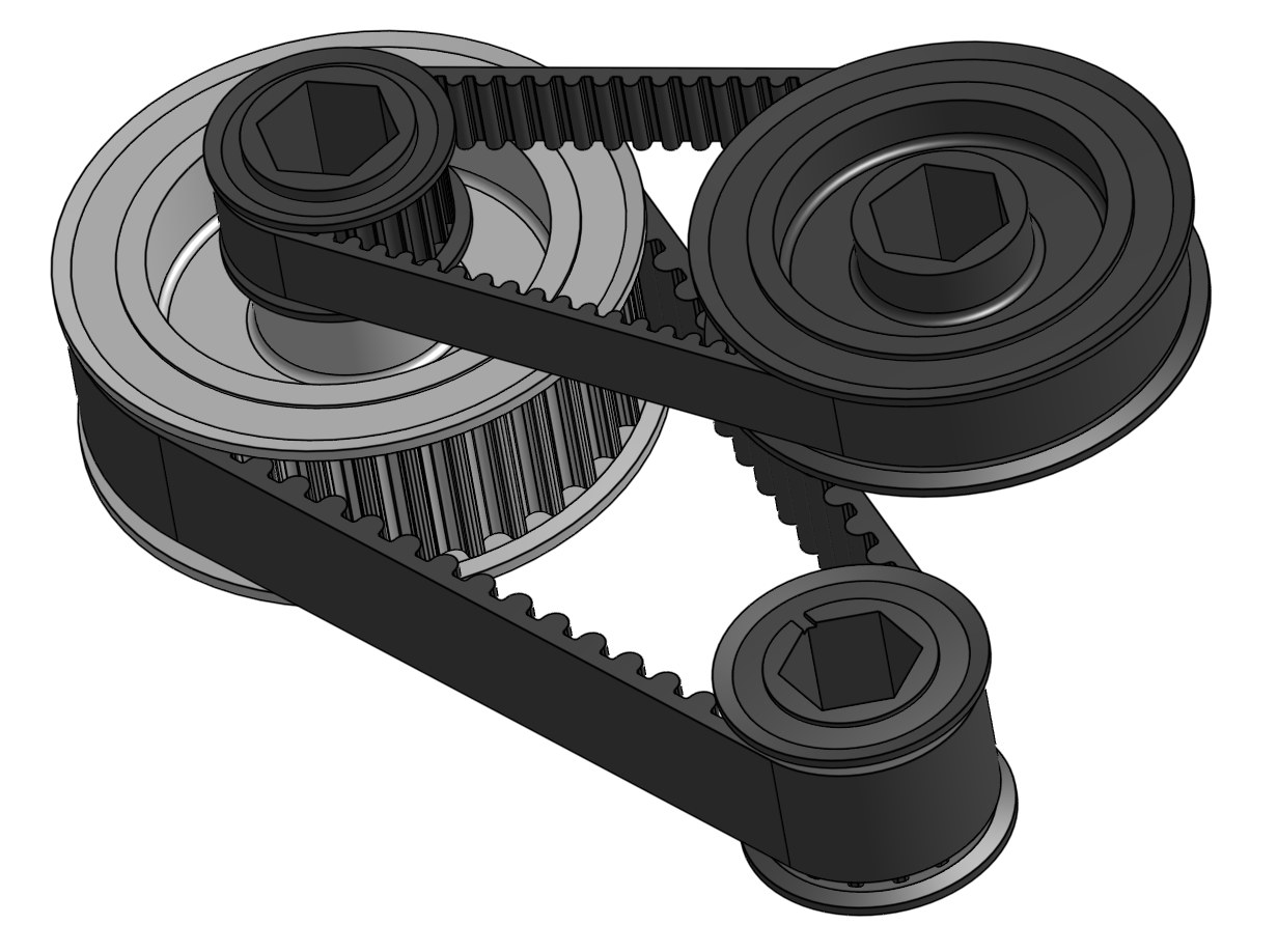
Belts + Pulleys
Power is transmitted via a flexible belt between two pulleys of different tooth numbers.
Advantages
- Simple, low-cost
- Lightweight
- Quiet
- Natural vibration-damping
Disadvantages
- Lower load capacity due to belt slip
- Lower efficiency
- Limited reduction raios
Cycloidal Drives
An eccentric cam drives a cyloidal disk. The cycloidal disk meshes against pins on a ring gear, reducing the speed through rolling contact.
Advantages
- Very high load capacity
- Low Backlash, leading to high accuracy
Disadvantages
- Complex mechanical assemblies
- Lower mechanical efficiencies at high speed
Strain Wave Drive
Strain Wave Gears use a flexible spline, an elliptal cam (to generate the wave) and a circular spline.
Advantages
- Very high reduction ratios (300:1 in a single stage is possible)
- Zero Backlash
- Compact
Disadvantages
- Limited Torque capacity
- Sensitive to overload and wear
3D Printability
Given the above options, it's important to again note that the aim is to FDM 3D print whatever speed reduction method I choose. This changes the playing field a little bit and makes the choice a little easier given this constraint.
If a gear was to be chosen, the herringbone gear would be best since its main drawback is the manufacturability using traditional methods. With a little bit of printer tuning, you can print high-quality, strong, herringbone gears. I have tried this in the past and got something working relatively well. Here is a video of a previously made gearbox with the iPower motor:
A Herringbone Gearbox - Fully 3D Printed
Harmonic and Cycloidal drives appear to be 3D printable. I've never tried but other people on the internet have, with varying degrees of success. My gut feeling is that the size requirements of what we are aiming for would mean the tolerances would be really hard to get right with FDM printing, and the number of parts makes that problem worse. Increasing the number of parts increases the number of mating surfaces, which increases the number of tolerance-critical parts, which majorly increases headaches.
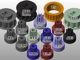
Belt and pulley systems are easily 3D printable. There are many different types of pulley designs, some of which are easier to print than others. You can download GT2 3D models and print them straight away, or you can spend the time and painstakingly model the correct pulley geometry, convincing yourself that it was worth the time and that it was enjoyable (guess which method I have done previously!). We have used belt and pulley systems in the past, and struggled with belt slippage but I have a solution to avoid that problem potentially. You'll have to come back to my next blog post to find that one out!
Reduction Requirements
Through some highly-educated guesstimation, we are aiming for a top linear speed of roughly $2 \, m/s$, and would like to be able to achieve this speed in around $0.5 \, s$, leading to a required acceleration of $4 \, m/s^2$. The main goal is slowing the motor down, and by doing this the torque increases, providing better acceleration and more "grunt". We can use the no-reduction speed and the desired speed to calculate the required gear ratio:
\[ G = \frac{v_{no-reduction}}{v_{desired}}\]
\[ G = \frac{8.9}{2.0} = 4.45 \]
So, we need to be able to achieve a $4.45:1$ reduction using one of the above methods, whilst being able to easily manufacture the complete reduction system, and minimising backlash. The belt drive ticks pretty much most of those boxes, with the exception that a $4.45:1$ reduction is actually somewhat non-trivial to do with a single belt without eating up way too much space.
Introducing BeltBox™
So if its hard to get the required reduction with a single belt stage, why not two belts? Well, I haven't come up with an answer to that question yet so I'm pushing ahead with that route (please shout if you know of a good reason why this is a terrible idea!), the plan is to do two identical stages as I believe this is what will require the least physical space. There are a few design requirements, the most important of which are:
- As small as possible in X/Y dimensions (Forward/Right)
- Cheap to manufacture/build
- High efficiency
- Modular
Given these constraints, I'll start sketching out some designs and playing around in SOLIDWORKS to get some concepts going. I plan on 3D printing as many of the components as possible (including the pulleys) to keep things quickly iterating and cheap, next post will have a prototype BeltBox™ (not really trademarked :( )