Motor Control Board Motor Test
"A blog to hold us accountable for the lack of robotic project progress" - well that's worked flawlessly hasn't it...
We're not dead, nor have we been completely idle, there's just been a lot going on in the background for both of us, with Christmas & new years, traveling, moving house, and much more. But I'm finally back on track with some proper progress on the robot to report, so let's get into some of the latest developments, as the moment of truth has arrived: will the, albeit slightly modified, hardware actually spin a motor?
It's Alive!
So the first success to talk about is working communication between the STM microcontroller and the FPGA. It doesn't look like too much as a few lines of debug log, but this was the cumulative effort of a solid month or two of FPGA development taking up all my spare time, so it made me pretty happy when I finally saw it.
So, what's actually going on here? Well I've cleaned up the help command with some proper padding so that it looks nice, but more impartantly I've added a few FPGA commands to the bottom of the list:
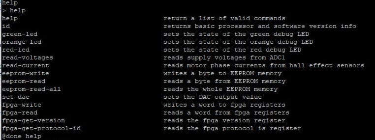
What do they do? At the surface level, fpga-read and fpga-write are fairly self explanatory at least, used for reading and writing a 32-bit word to one of the fpga registers.
The protocol I've implemented has a 1-byte command with one bit for indicating read/write and 7-bits of address space. The address space is further split, half for read-only "status" registers, and half for "control" read/write registers. I'll go into more detail about the specifics of this protocol below, but for now the details don't matter too much.
Of the 128 possible registers in the address space, I've only implemented 32 of them to save space on the FPGA, 16 status (0-15) & 16 control (64-79). If I need more later I can change that, but currently I think even this many is far more than I'll end up using.
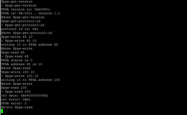
"fpga-read" just takes one argument, the adress to read from. "fpga-write" takes two, an address and the data to write to it. Ignoring the first two commands in the image below for now, it shows successfully writing an then reading from control register 1 (address 65), and a similar attempt with address 100 which fails on the read command as the register doesn't exist.
The first two status registers hold specific values that indicate the version of the fpga configuration the has been programmed so that the STM can check it is talking to the correct thing, and a protocol id so that it can check it correctly knows what the other registers mean.
I could almost certainly get away with not having this and being careful with what I program onto everything so that nothing gets out of sync with mismatched versions. It's nice to have something to confirm that I haven't messed anything up though, even more so if we end up making two robots like we did last time.
Anyway, these two commands read these specific registers and check them against expected/compatible values hard-coded into the software. The first two commands in the picture above show these commands correctly verifying that the values read were as expected.
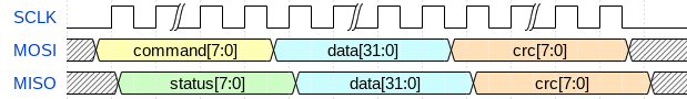
STM-FPGA Protocol
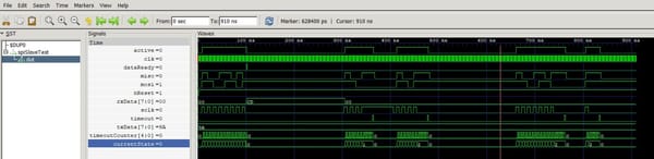
So the STM to FPGA is implemented of a 3-wire SPI peripheral (SCLK, MISO, & MOSI), with the STM as the master. To save pins I don't have a chip select, so the FPGA will just time out if it doesn't get an edge on SCLK within a pre-defined time which should allow it to recover if ever they get out of sync.
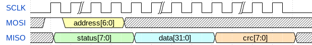
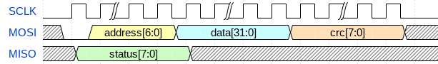
For what it's worth, if you ever happen to want to create some nice looking timing diagrams, wavedrom.com is pretty neat.
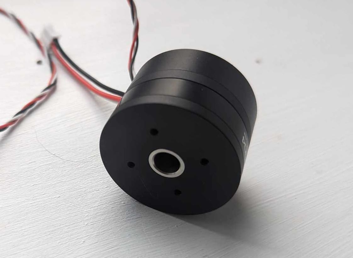
Position Sensing
More updates to the FPGA allow it to now read the position out of the AS5048A hall-effect position encoder, and additional software updates to the STM to read the relevant registers provides the following output:
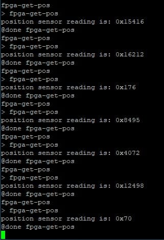
So ignore the "0x" - the output is actually in decimal in that screenshot - I was so surprised that this all worked first time that I didn't even realise the print statement was formatted wrong. But it does actually change in line with expectations when I move the motor/encoder! It has a 14-bit output (16384 steps per full mechanical rotation) so the value changes by around 4000 when I spin the motor by 90 degrees.
It's worth noting that with 7 pole pairs, the effective resolution gets reduced down to around 2340 steps per electrical rotation. Still, that'll be plenty accurate for the motor control I'm aiming for.
Motor Stepping
I added a register to allow control of the motor driver signals from the STM, added some rudimentay motor control functions and hey presto, the motor spins (albeit driven more like a stepper motor rather than with FOC).
Nothing to show off here because I went straight onto the slightly more exciting next step.
All Together Now
So I had originally made an oversight regarding the mechanical design of the encoder board. While it would fit into the motor enclosure, the motor couldn't spin more than about 30 degrees before hitting the connector on the board. Oops.
However, when making the cable to connect the encoder to the motor driver, I got frustrated by the crimps and decided to remove the connector and just directly solder the wires to the encoder board. This incidentally solved the previous problem as well as my inability to crimp, and so enabled a preliminary self-test/calibration routine.
The motor is driven in open loop until the encoder passes the zero point, after which it performs another full rotation while counting how many cycles/pole-pairs (electrical rotations) it has to drive through to complete the full mechanical rotation. This allows the driver to either confirm that the motor it has conforms to its expectations, or for it to automatically detect the motor pole-pairs. Regardless, it's very exciting to see the new driver finally spin a motor.
What next?
Onto FOC (field oriented control), mechanical integration testing with a gearbox/belt drive, some CAN bus development, and a hardware re-spin to make my mods permanent. More on these another time (hopefully without a multiple month long gap in between)!