Modular Motor Driver Rev-B
So it's been something like 6 months since I started writing this post, adding bits and pieces as I found errors in my design, but for the most part it was actually complete after about a month. Now that I've spun a motor, albeit not very well yet, I think it's pretty unlikely I'll need to make any other changes and so I can now release revision B of the design! With that said, back to past me:
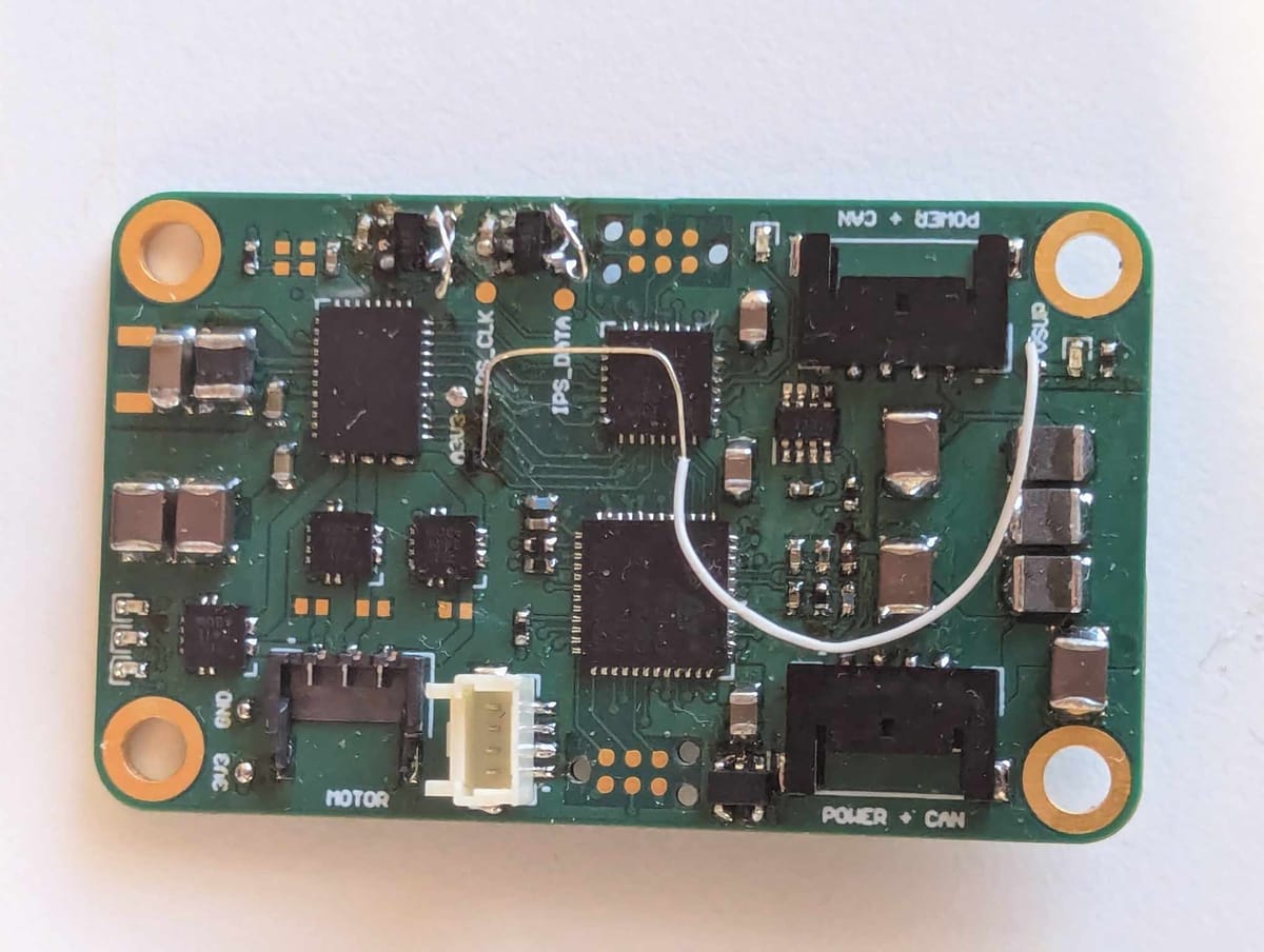
As evident by the criss-cross of bodge-wires now present on the Rev-A motor driver PCB, after a few weeks of testing I have accrued a handful issues with the initial design. Nothing so far that can't be bodged on Rev-A to continue the development, but easily enough that I don't want to be modding 10 copies to this level - so begins the Rev-B re-spin!
Rev-B Updates:
So what have I changed? Well mostly it's fixing a few errors/bugs in the design, but also a couple of slight improvements that aren't strictly necessary.
- Fixed broken footprints (LVDS & EEPROM)
- Fixed boot 3V3 issue
- Inverted Vsupply sense resistors
- New hall-effect current sensors & layout update
Misc Small Issues
There's not too much to say about the incorrect footprints, I had the wrong pinout for the LVDS transceivers, and the wrong size footprint for the EEPROM IC - they're fixed now. In the short term, I managed to get the EEPROM in place without shorting anything out, and the LVDS ICs are now tipped upwards and have the incorrect pins rerouted with some criss-crossed bodge wires.
I of course had plenty of software issues, almost all resulting from PEBKAC - "problem exists between keyboard and chair", although there were one or two that I think were induced by non-ideal manufacturer documentation.
As for the other issues & updates, well, they're a little more interesting.
3V3 Boot Issue
I probably should have read the datasheet more thoroughly on this one. But either way I probably wouldn't have gotten this completely right the first time anyway.
The Symptom
So this was a pretty fundamental issue, and the first one is discovered when testing the board: the 3.3V rail wasn't coming up when I gave it 24V in. It wasn't hitting the current limit and nothing was getting hot, so it likely wasn't a short circuit.
Chasing the Problem
The first thing I tried was powering the 3V3 externally. I tacked some wires onto the 3V3 & GND test points, gave it 3.3V, and to my surprise it kind of worked. It didn't hit the current limit I'd set on the power supply, and I was able to successfully program the STM32. This proves that it definitely wasn't a short circuit on the 3V3 rail (that could have perhaps triggering an overcurrent protection on DRV8316 to kick in), so it seems to be an issue specifically with the DRV8316 buck regulator circuit.
Unfortunately the DRV8316 buck regulator is really simple, it's pretty much just an inductor and a capacitor that are required externally to make it work. Time then to delve back into the datasheet to see what might cause such an issue, and it didn't take long. Looking through the pinout table I found a line that looked a little suspicious:
"Driver nSLEEP. When this pin is logic low, the device goes into a low-power sleep mode".
After a little more digging I was able to confirm an issue with my design - I had assumed the nSLEEP would only control the motor drive portion of the IC, but it also shuts down the buck supply when active (low). I had simply connected this pin to a pin on the FPGA which results in a bit of a catch 22 - the FPGA doesn't have power so it can't enable the 3V3 supply, and the 3V3 supply isn't enabled so it won't power the FPGA.
Down the Rabbit Hole
Turns out there's even an internal 150-300kohm pull-down resistor on this pin, so even if the FPGA was configured to drive the pin high (which it isn't because it doesn't get power so I can't program it), it would still never get the chance to do so. This begs the question, how do they expect you to pull it up normally? Checking the absolute maximum ratings of nSLEEP it can only handle 5V so presumably you're not meant to tie it to the input supply voltage. On further inspection, the A3V3 20mA LDO is not disabled by the nSLEEP pin, and so can be used to tie it high and default the 3V3 buck regulator on.
A quick bodge wire later, and the A3V3 test pad was connected the the nSLEEP pin. I connected 24V again, and? ... nothing. I had a pretty good idea of the cause this time around though, and a quick experiment confirmed it.
Light at the End of the Tunnel
Pulling nSLEEP up to A3V3 did nothing, everything stubbornly remained at zero volts, but by instead "jump starting" the 3V3 rail (powering the 3V3 supply for a moment and then removing the external power supply) it booted! So what's still going wrong? Well the A3V3 is connected to VDDA on the STM32, but without the main 3V3 supply present it tries to power the STM's VDD rail as well. 20mA isn't going to cut it for that and so the A3V3 rail collapses, and with no A3V3, no nSLEEP pullup. No pullup, no 3V3.
So, I could use the A3V3 supply exclusively for the nSLEEP pullup, but that's not going to be an easy mod. Also I like having a separate LDO regulator for the analogue functions of the PCB. So I'll tie nSLEEP up to the supply voltage then, except the nSLEEP pin can only tolerate a maximum of about 5V. I considered a voltage divider , except that the range that the threshold (minimum) voltage and it's absolute maximum don't leave as much range on the supply voltage as I'd like, which led me to my final solution.
The Solution
Eventually we reach my final fix: a 200k pullup resistor paired with a 3.3V zener diode to ground (in parallel with internal pulldown resistor).
To get the current board booting without a jump start, I went for a tiny 0402 resistor and diode for the mod. This was a very frustrating experience to solder, with each connection having such little thermal mass that the next connection would often disconnect the last, resulting in an incredibly dodgy bodge wire.
After a few weeks though I came back and swapped the 0402 resistor for a 1206 one, as well as tidying up the bodge wire itself, to make the mod a little more mechanically robust. Both versions are shown below in all their sticky, fluxy, glory. Regardless, it boots fine now with a range of input voltages, so the hardware testing can continue.
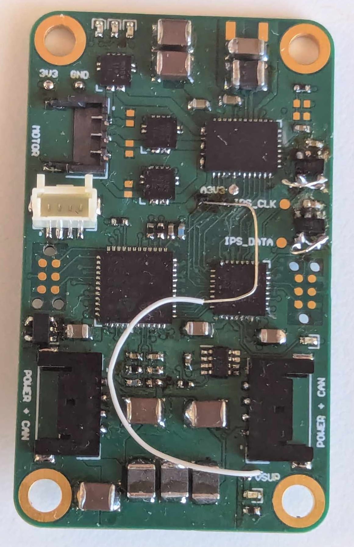
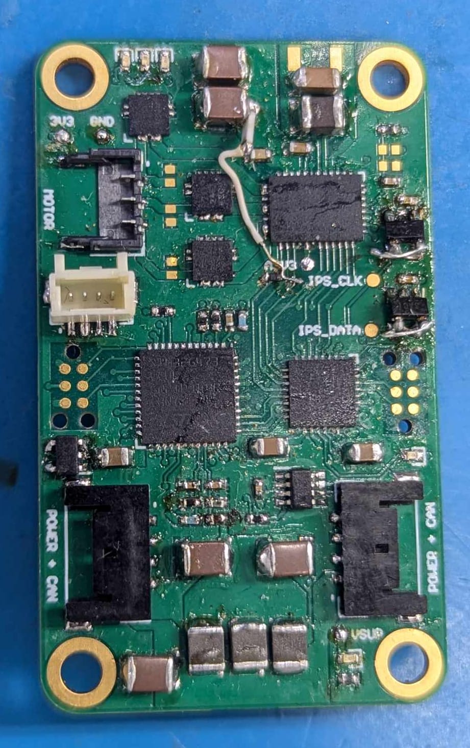
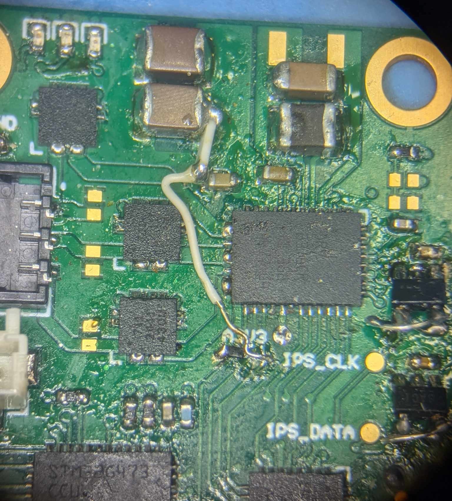
Left: original 3V3 boot fix bodge wire, Middle: "improved" 3V3 boot mod wire, Right: Zoomed image of mod wire
New Hall-Effect Current Sensors
In comparison to the boot issue, this isn't such a big deal. But while I'm making updates I thought I may as well take the opportunity for some quick and easy upgrades. Honestly, I'd decided I wanted to replace them before I'd even read the current out of the existing ones.
The new ones have two hall-effect sensors integrated into each sensor which are mounted in alternate axes, allowing the sensor to better reject common-mode/stray magnetic fields from something like a nearby motor. They also have a slightly different current range and are non-ratiometric now, but mostly I wanted them for the stray field rejection improvements.
Re-layout
This wasn't a complete do-over, but I did go back and improve a handful of areas to reduce the parasitic inductance in some key areas, overall improve the ground reference planes, shifted the layer stackup slightly, etc. Most of this is a bit too in-depth to properly get into here, but maybe at some point I'll post a guide with some of the good-practice layout tips & tricks I follow.
Rev-B Motor Encoder Boards
It's not just the motor driver PCB that's getting a re-spin, the motor encoder boards are as well! What can I say, I'm just really good at making stupid mistakes.
The LVDS chips have the same footprint issues that the other board did, and so Rev-A has the same tilted & rewired mod to facilitate testing up until this point.
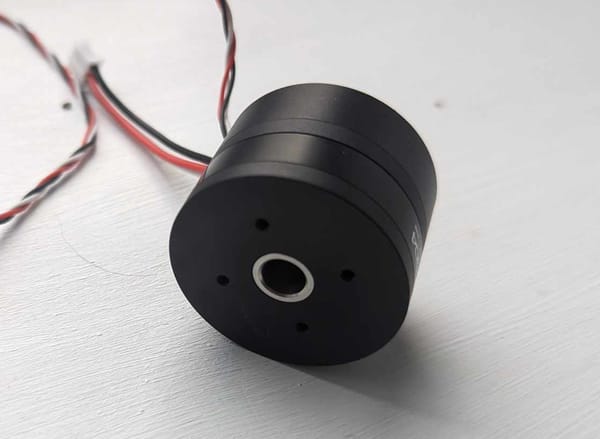
Even worse though, the power & comms connector doesn't quite fit. Or rather, it does fit but only in some orientations. The magnet carrier on the rotor of the motor, used to create the changing magnetic field that the hall-effect encoder measures, has a hexagonal mounting flange. At least I think it's a flange? - flange sounds right to me, but I'm no mechie...
Anyway, the hexagonal flange is just the right size that when a flat side aligns with the connector everything is fine, but when a point of the flange is aligned then they clash. At the moment this gives me about 20 or 30 degrees of rotational freedom, plenty to perform some testing it certainly needs fixing before I can do any closed loop motor control.
For Rev-B I've moved the connector so it's out of the way, but I might just end up soldering the bare wires onto the board without the connector anyway.
Just the two issues on this board, although given the size and complexity of this board, that's probably not something I should be particularly proud of.
Next steps?
The next few posts should be quite exciting - FOC motor drive, new PCB designs, CAN bus communication, etc. Hopefully it doesn't take me months to get them working this time...