Modular FOC Motor Driver
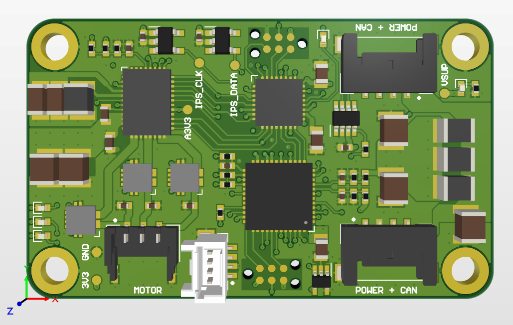
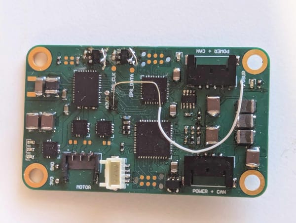
So it's been a about 3 months since we started work on the next design iteration, and what have we got to show for it? Well I've been busy in Altium, and the first prototype of the new motor controller PCB has been delivered. There'll be plenty to talk about over the coming weeks as I begin to test, debug, and generally put it through it's paces, but for now there's plenty to dig into with the the features I've included and design decisions I've made this time around.
What Makes it Modular?
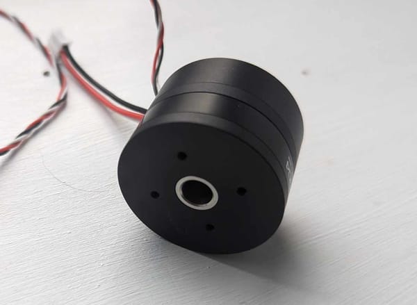
The first big change compared to the motor control board I made for the lasy robot is that it can only control a single motor. A single motor per controller greatly simplifies a lot of the processing (at least from my hardware-centric perspective), and makes the system much more extensible - need another motor, just add another copy of the same board! It also distributes the processing and allows the motor controller to be integrated into a motor/gearbox/wheel assembly - to be determined whether we actually end up doing this.
Further to this, all the non motor related functions have been removed. Previously the motor controller performed power management with a load switch to control power to the raspberry pi. This will all be moved to the pi-hat so that nothing needs to be duplicated on the motor controllers.
While not strictly required, they also have a CAN bus & power supply pass-through connector. This allows them to be daisy chained, both for simpler cable management, but also to prevent the pi-hat from limiting how many motor drivers can be added to the design. The plan at the moment is to have two connections on the pi-hat for the CAN + power bus, one on each side, and then each motor driver will daisy chain the connection to the motor controller next to it, and then onto the Battery Management System (BMS) on one end and an attachment controller of some variety on the other.
And What Does FOC Mean?
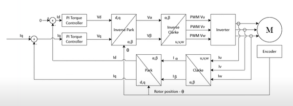
FOC stands for Field Oriented Control. It is a method of motor commutation where the magnetic field created by the three motor phases is modulated such that it continuously leads the permanent magnets by a set angle.
Normally this angle is set to lead the rotor by 90-degrees (quadrature axis) in order to maximise the torque output and efficiency of the motor as all of the field strength generated is acting to spin the rotor, with none in the direct axis (in line with the rotor). In more advanced implementations the angle can be reduced to cancel out some of the back-emf generated by the motor rotating that prevents higher speeds on a voltage limited system, this is called flux weakening.

Compared to trapezoidal control (commonly used by RC hobby motor ESCs), FOC results in a smoother motion of the motor with less torque ripple as the motor moves between poles. Because the rotor angle must be accurately known for FOC, a position sensor is required (sensorless FOC is possible, but it's a bit complicated for me at the moment), it also gives far better slow speed control as well.
Key Features
So with all of that out of the way, let's take a look at some of the features that I've included this time around - there's a decent amount for a 30x50mm board. I've really leant into the QFN packages this time to keep the size down, as compared to the mostly QFP/SOIC designs I made for Pi-Wars 2024 - I'm not quite ready for assembling BGA/WLCSP packages by hand just yet.
STM32G473 Microcontroller & MachXO2 FPGA
Perhaps a little overkill, but I wanted to make sure the processing hardware didn't impose any limits on the potential for the motor controller due to my lack of skill on the software side of things. So it's pretty much the same microcontroller as last time but it only needs to control one motor. Plenty of peripherals and flash memory available for me to go absolutely wild with inefficiency.
As if that wasn't enough, on top of the STM32G4, it has also an FPGA to handle the motor Input Position Sensor (IPS) and the motor PWM. Partly this is motivated by my desire to play around with a HDL again, but also should make the motor control loop a bit snappier & more synchronised than before. This is something that I may well end up regretting in a few months time, but it would be easy enough to remove it for Rev-B if things go that way.
I might make write a post going into more detail on FPGAs at some point, I imagine most people reading this won't have used them before (and many people might not even know what the acronyms FPGA & HDL stand for...)
DRV8316C All-in-One Motor Controller
Now this was a nifty little find. A ridiculous amount of features integrated into a relatively tiny package, it's the chip that really makes the small board size possible.

Integrated gate drivers and MOSFET half-bridges for 3-phases for a peak of 8A and 40V. We'll be sticking with a 6s lithium battery (~24V), and currently planning to use motors well below that (<1A peak motor current), but this gives plenty of room for upgrades down the line.
Already the above would be decent for the 5x7mm package, but it then goes on to include motor phase current sensing. This can be used for the FOC control loop, but would prefer to use hall-effect rather than shunt resistors for my current sensing - more on this later. No worries though, because the integrated current sensing can be used a a hardware over-current protection for the motor. With the "ILIM" pin connected to the DAC on the STM32G4, the limit is software configurable! Hopefully this will prevent the tragic & premature deaths of a few motors this time when I inevitably mistype PWM values into the debug command interface.
And if all that wasn't enough, it has one last party trick. While perhaps not that exciting, it's the thing that still surprises me the most about it. It manages to cram in a 3V3 switching buck regulator with a 200mA output, and an analog 3V3 20mA LDO as well! By avoiding anything that couldn't run directly off of 3.3V like the plague, this meant that I didn't need any other power supplies on board. Just like that, all the "high power" functions of the board are dealt with in one fell swoop.
Hall-Effect Motor Phase Current Sensing
The DRV8316 does offer integrated current sensing as well, but you can only use the hardware current limit or the current sense outputs, not both. As above, I like the idea of having a dedicated hardware protections to prevent software (or operator) based faults causing significant hardware damage.
As a happy side-effect to this, implementing my own external current sensing allows for the use of hall-effect, rather than resistive current shunt, based current sensing. I might talk about this in more detail in the future, but put simply hall-effect is nicer for in-line phase current sensing as it is not susceptible to the measurement spikes caused by common mode voltage change at PWM edges like resistive shunt sensing is. They are, however, susceptible to stray magnetic fields that could perhaps be generated by something like a rotating motor in close proximity (a small package inverted differential hall-effect current sensor would be really nice).
LVDS Input Position Sensor Interface
As part of my initiative this time around to make all inter-board signals differential twisted pairs, the IPS interface now has an LVDS transmitter & receiver pair. Perfect for a BiSS interface, like we used last time, with MA out and SLO in. Since it goes into an FPGA though, it's infinitely re-configurable.
At the moment I'm looking at using an AMS AS5048A, which uses a normal SPI interface. This utilises a standard SPI interface, and frustratingly it doesn't tolerate nCS being tied low. As such I added two single-ended signals to the interface for nCS and MOSI (although these can be reconfigured to be anything I want later on). This somewhat violates my differential-only board-to-board connection policy, but the connector is already has 8 circuits and I'm short on space. They should be fine like this though - chip select isn't nearly as high a frequency as the clock and data signals, and MOSI will be tied low most of the time (should be a one-time configuration at boot, if that).
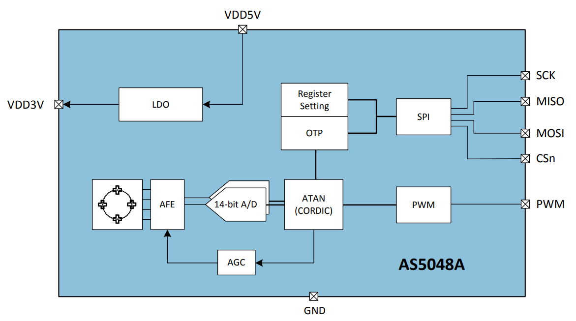
Like I've said already, this inteface is incredibly flexible due to the FPGA, so the details can be worked out much later when I get into the FPGA development.
CAN Bus In & Out
As discussed above, the CAN bus & power supply interface is passed through the board so that they can be daisy chained. As there will be nodes on either end (BMS on one end and a misc attachment control board on the other), CAN bus termination resistors are not required on any of the motor driver boards, making them fully interchangeable & modular. The CAN bus transceiver is fairly standard, but takes a 3.3V supply and is in a fairly small package.
2kb EEPROM Memory
A bit of an afterthought, but 256-bytes of non-volatile memory for the storage of settings and calibration data is certainly nice to have. I probably could have messed around with using some of the STM32 flash for this purpose but it doesn't take up much space and is really easy to use.
Debug UART, Status LEDs, & Tag-Connect Programming
These perhaps might be stretching the definition of a feature, but are worth a mention at the very least.
Last time the debug UART ended up being the primary method of communication between the motor controller and the pi. This time, with 4 separate motor drivers, control over UART will not be an option. As such I'll be aiming to no-fit the connector on most of the boards I assemble since everything will go over CAN once it's up and running properly. Until then though, UART will be indispensable in getting everything working to begin with.
Status/indicator/debug LEDs are something I sorely neglected last time. A mistake I have vowed not to repeat on this board. 3 LEDs (red, orange, and green) are connected to the STM32G4, and one orange LED is connected to the MachXO2 FPGA. I would have probably added another to the FPGA if I hasn't run out of pins on it, but one should do the job considering it also has an SPI bus to the STM for further debug & status reporting.
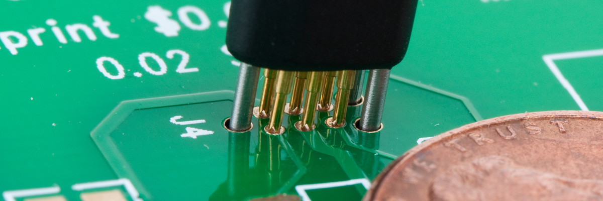
Tag-Connect! The first time I used these was on the last motor controller, and I've fallen for them - hook, line, and sinker. Such a small footprint, and so easy to use, but my god are they expensive for hobby projects. But the more you use them the better the value gets - so this board has 2. I could maybe have gotten away with just one, and I did consider putting both the STM and the FPGA on a single JTAG bus, or having the STM configure the FPGA, but in the end I decided both options were more effort than they were worth and put down 2 sets of Tag-Connect pads.
Next Steps
Now begins the slog of software & FPGA development, hardware integration, & board-level testing. The first steps will be the getting the basic functions of the board working - things like ADC voltage monitoring & current sensing from ADCs, EEPROM I2C interface, DAC ILIM voltage output, sending & receiving CAN messages.
If all that works then I'll more on to implementing some of the more advanced features - things like SPI communication to the motor driver & FPGA, implementing a comms protocol over CAN, loading & writing configuration settings to EEPROM, reading the IPS for the FPGA, full FOC motor commutation, etc. etc.
That'll be plenty to keep me occupied for a while yet. Once we've got a motor spinning again with the new driver, and mechanical testing of the gearbox design & output torque/speed is underway, I'll start looking into the new pi-hat design. Even with two years ahead of us it still feels like there's so much to do...
