FOC Motor Control!!!
It actually spins 😲
It's been a long road to get back to the same level of motor control that I'd achieved around a year or more ago, but the quality of electronics architecture, PCB design, code, and many other aspects, makes it worth it.
At least it makes it worth it in my mind. Perhaps that's the only place it ever made sense, but I don't care - it makes me happy.
Field-Oriented-Control
I gave a bit of an overview about FOC about it in a previous post, but I'll quickly recap for those that might have forgotten (and can't be bothered to go back and re-read it). I'll also go into a bit more detail about how it works and how I've actually implemented it (ew coding).
If you just want to to see a motor spin then skip further down and you can witness the motor spinning in all it's field-oriented smooth & efficient glory.
What Is It?
Field Oriented Control (FOC) is a method of brushless DC motor commutation where the magnetic field created by the three motor phases is modulated such that resulting field angle continuously leads the permanent magnets by a set angle.
Trapezoidal control is another brushless motor control method which, in contrast, steps between the phases without modulating between them. This causes much larger torque ripple as the angle between the magnetic fields of the stator and rotor shrink and grow as the rotor spins and the energised phase changes.
The animation below better articulates the difference between these two methods, showing how the FOC stator field (generated by modulating current through the stator coils) is constant in magnitude, generating a constant torque on the rotor.

Normally in FOC, this angle is set to lead the rotor by 90-degrees (in the quadrature axis) in order to maximise the torque, and therefore efficiency, of the motor as all of the field strength generated is acting to spin the rotor, with none in the direct axis (in line with the rotor). In more advanced implementations the angle can be reduced to cancel out some of the back-emf generated by the motor rotating that prevents higher speeds on a voltage limited system, called flux weakening, but that's beyond where I'm at right now.
In order to perform this control method, the motor phase currents must be known so that they can be modulated, and the rotor position must be known so that it can be correctly lead.
Sensorless (position) FOC is possible, but it's a bit complicated for me at the moment. It's also worth noting that with a 3-phase motor you only really need to know the current of 2 phases as you can work out the third assuming there's no leakage of current from the motor, but I've added three to allow for redundancy & error checking - no expense spared here.
What's All The Fuss About?
Compared to trapezoidal control (commonly used by RC hobby motor ESCs), FOC results in a smoother motion of the motor with less torque ripple (effectively zero) as the motor moves between poles. This gives better efficiency and, in general, smoother rotation - speaking of which:
It gives much better smooth & accurate slow-speed control of the motor. Adding a position sensor to a trapezoidal control system will give some improvements, allowing slow speed control, but it will still get "lumpy" at a certain point unless you start doing some sort of modulation and if it isn't field-oriented then you start getting pretty severe torque ripple.
Finally, it gives "easy" torque, velocity, or position-based control. Maybe it's only really torque-based control that you get as an "extra" with FOC, but it's relatively easily to implement the very useful velocity and position target control schemes (over the top of the FOC torque control loop) which is very nice to have in many robotics applications.
The Boring Maths Bit
Transforms! It could be done without them, but they make FOC so much more efficient & effective than it would be otherwise that it just doesn't make sense to do it without them.
Essentially, for constant velocity control (equivalent to constant non-zero torque control with a constant motor load) the target field is constantly changing in angle as the rotor spins. This makes the control difficult as, despite the target drive parameter (torque/velocity) being constant, the output value required to achieve this is constantly changing. Ideally (at least for a simple control system), for a given load there should be a single output value that will achieve the desired outcome which isn't constantly changing so that the control system can hone in on it. The control system then only needs to react when there are changes to the external conditions, such as the motor load, which is usually relatively slow compared to the rate that the control loop runs at.
So, what do the transforms do? Well, the first (the forward Clarke transform), takes the 3-phase space (U, V, & W, which are 120-degrees apart from each other) and turns them into X-Y space. This is fairly simple maths, but lays the groundwork for the next step. It's performed as follows:
X = (2*U – V – W) * (1 / 3)
Y = (V – W) * (1 / sqrt(3))
There's also an equation for calculating the Z axis, but this should always be zero since the U, V, and W motor phases are a closed system and should therefore sum to zero. A magnetic field in the Z axis would also be counterproductive for a motor - it would be verging on a solenoid at that point - but here it us for completeness:
Z = (U + V + W) * (1 / 3)
Next is the real game changer (the forward Park transform), which takes the X-Y space and transforms it into Q-D space. These stand for the quadrature axis (perpendicular to the rotor's magnetic field, and the direct axis (aligned with the rotor's magnetic field. They are calculated as such:
D = cos(theta)*X + sin(theta)*Y
Q = cos(theta)*Y - sin(theta)*X
This requires trigonometric functions, which are traditionally quite computationally intensive, however the CORDIC algorithm can be used to approximate it fairly well for much less effort. It also gives you the sin & cos values together in a buy-one-get-one-free sort of situation, and even better, you can re-use those values for both the equations above (and the ones below). Alternatively, a look up table could be used for each possible value if the angular resolution isn't too high.
Anyway, the beauty of this is that the control loop can be run in the Q-D space (after transforming the measured phase currents into X-Y space, and then into Q-D space using the rotor angle). This means that for a set target torque (or target velocity with an unchanging load) the target Q-D values don't need to change (the changing rotor angle, theta, used in the transforms then generates the correct modulated U, V, & W outputs). This allows for a much simpler control system (usually just a PI controller), which is then transformed back into 3-phase space using the reverse/inverse Park and Clarke transforms so that they can be applied to the motor.
For completeness, they are as follows:
X = cos(theta)*D - sin(theta)*Q
Y = sin(theta)*D + cos(theta)*Q
U = X
V = (-X / 2) + (sqrt(3) / 2) * Y
W = (-X / 2) – (sqrt(3) / 2) * Y
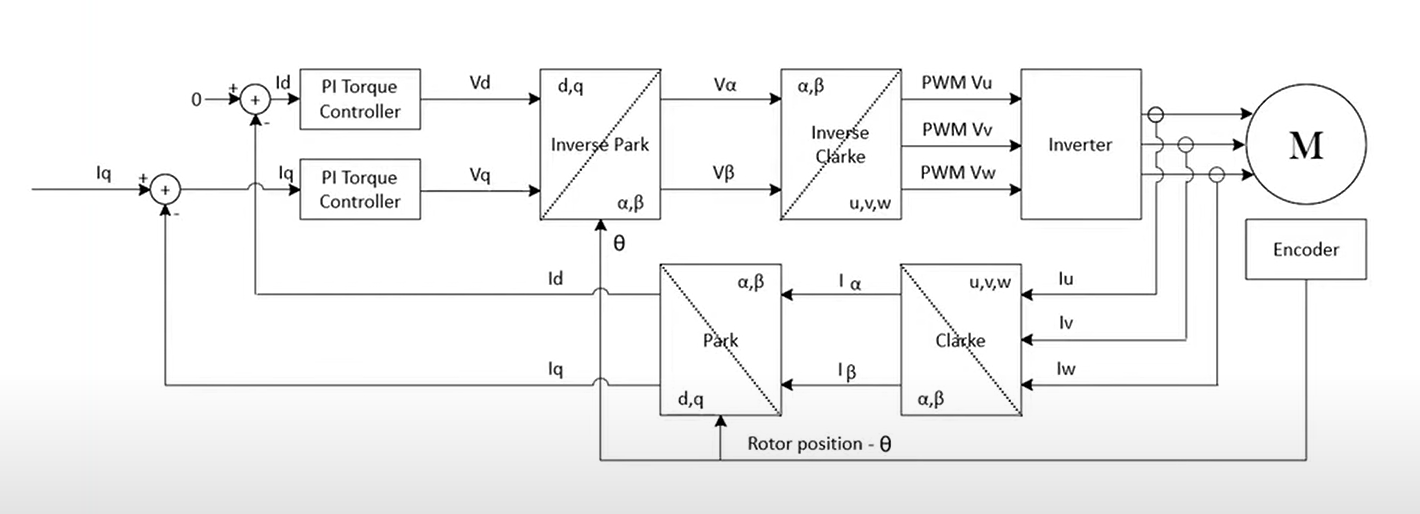
After the control system has performed the conversion from measured current to desired PWM duty cycle output, these are sent to the symmetrical PWM outputs that then drive the motor phases high/low and it just works!
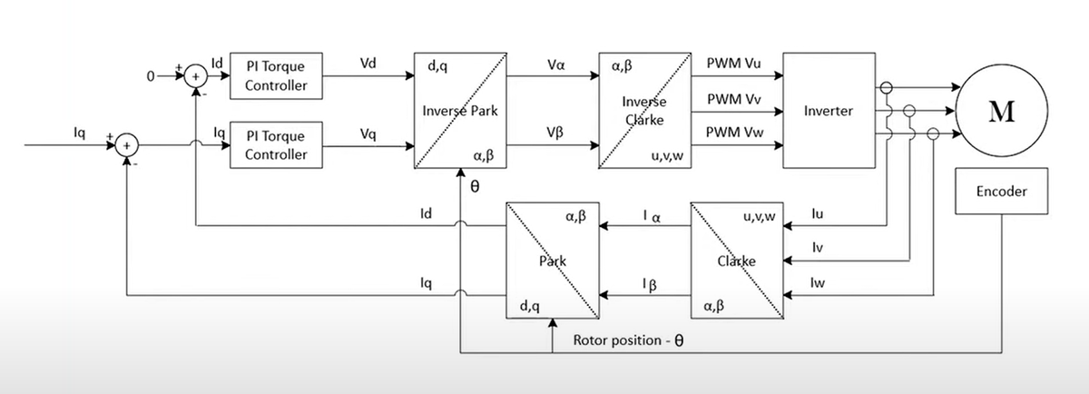
The diagram below might perhaps give a slightly better idea of what's going on? If not here are a handful of useful YouTube videos you can go watch if you're in the minority of being confused but still keen to learn more.
Random other YouTube FOC videos that probably explain it better than I have:
- Texas Instruments: Field-Oriented Control
- Texas Instruments: Field Oriented Control of Permanent Magnet Motors
- Jantzen Lee: Understanding Motors (Playlist) - episodes 8-11 are probably the most applicable for FOC in particular
The Fun Bit
The bit you've all been waiting for (or skipped to), a motor turning:
Motor Spinning in FOC constant torque control (roughly 100mA constant current)
I think this is cooler in person, so you'll just have to make/buy your own if you want to bathe in the true glory of field-oriented motor control.
It's also not quite as cool as it could be because I haven't implemented velocity or position target control systems yet. As such, with constant torque, it will slow down when loaded and it's difficult to get it spinning at slow speeds (since there's a fine gap between slow and stalled) so it doesn't look all that impressive. Torque control (as far as I'm immediately aware) allows for fun things like gravity compensation, but for most applications isn't that useful, and is just the enabler for good velocity/position control.
You can expect a post in the next few weeks (hopefully not months...) showing a motor in constant velocity control spinning really slowly & smoothly. I've also not tuned/calibrated a handful of things very well, so hopefully they'll be in better shape next time I show off motor control since it's not got much torque for ~100mA of current.
What Now?
Motor control works - so that's the motor controller completed, right?
Not at all. I need to write plenty more code so that everything runs properly using CAN rather than debug UART, as well as improving the efficiency in a bunch of areas to maximise the motor control performance. And then I need to build 10 of them (4 x2 robots + 2 spare). And then I need to get the pi hat and its many auxiliary functions working as well.
Funny how much work there is when you don't bodge absolutely everything.
We're at least getting to the stage that we can start doing some early electro-mechanical integration testing though, which should be good. It's such a nice feeling to be considering doing this more than a few weeks a competition deadline (although having a proper deadline at this point would be greatly appreciated - it's looking like we won't be getting a Pi-Wars 2026 either, finger crossed for 2027).
Maybe the blog is actually working, maybe we've finally learnt our lesson, or maybe just having years between deadlines makes it feel like we're making progress faster than we actually are.